Display Attached Controller @E.
Preface This hardware edition of the user’s manual describes system composition, specifications, and handling of the @E.Terminal. In order to operate the hardware properly, please read this user’s manual carefully. When using modules or peripheral devices, be sure to read the corresponding user’s manuals listed below. Title Manual No. Contents @E.Terminal for MC User's Manual FEH301 Describes functions and the usage of motion control content for @E.Terminal for MC.
Safety Precautions Be sure to read the “Safety Precautions” thoroughly before using the module. Here, the safety precaution items are classified into “Warning” and “Caution.” Warning : Incorrect handling of the device may result in death or serious injury. Caution : Incorrect handling of the device may result in minor injury or physical damage. Even some items indicated by “Caution” may also result in a serious accident. Both safety instruction categories provide important information.
Safety Precautions Caution ◊ Check the appearance of the unit when it is unpacked. Do not use the unit if any damage or deformation is found. Failure to do so may lead to fire, damage or malfunction. ◊ For use in a facility or for a system related to nuclear energy, aerospace, medical, traffic equipment, or mobile installations, please consult your local distributor. ◊ Operate (or store) @E.Terminal under the conditions indicated in this manual and related manuals.
Safety Precautions [General Notes] • Never bundle control cables nor input/output cables with high-voltage and large-current carrying cables such as power supply cables. Keep these cables at least 200 mm away from the high-voltage and large-current carrying cables. Otherwise, malfunction may occur due to noise. • When using @E.Terminal in an environment where a source of high-frequency noise is present, it is recommended that the FG shielded cable (communication cable) be grounded at its ends.
Revisions *Manual No. is shown on the cover. Printed on *Manual No. Revision contents Aug. 2008 FEH300 First edition Nov. 2008 FEH300a • Display part is changed from UG40 series to V8 series. • Accessory "Noise filter" is eliminated from controller hardware version "03" or later. Dec. 2008 FEH300b @E.Terminal (No contents installed) was added.
Contents Preface Safety Precautions Revisions Contents Page Section 1 General ..........................................................................................1-1 1-1 1-2 1-3 1-4 Overview of @E.Terminal for MC .................................................................................................. Appearance ..................................................................................................................................... Types ........................................
Section 1 General Page 1-1 Overview of @E.Terminal for MC ............................................................................... 1-1 1-2 Appearance ................................................................................................................. 1-2 1-3 Types ............................................................................................................................ 1-3 1-4 System Composition ..........................................................................
Section 1 General 1-1 Overview of @E.Terminal for MC The @E.Terminal for MC Display Attached Controller is an all-in-one programmable operation display and motion controller. Features: 1) The guidance function of the display screen allows you to easily set up parameters and positioning data previously set up by a dedicated machine. Also, it enables easy equipment maintenance.
1-2 Appearance @E.Terminal for MC is composed of a programmable operation display (the display unit) and a controller unit attached to the back of the display unit. The controller unit is attached with screws to the connector area of the communication unit at the back of the display unit, similar to the way in which the communication unit is attached.
1-3 Types • @E.Terminal for MC Product types Display size Specifications NP5M0101-5H4 12.1 inches NP5M0101-4H4 10.4 inches NP5M0101-3H4 8.4 inches • TFT color, 800 x 600 dots, DC power supply • Controller unit • Contents of the motion control (Screen data, built in software in the controller) • @E.Terminal (No contents installed) Product types Display size Specifications NP5N0011-5H4 12.1 inches NP5N0011-4H4 10.
1-3 Types • Auxiliaries and others Names Types Specifications Battery for display unit V7-BT Replacement lithium primary battery for the V8 series Replacement backlight for TFT V812-FL Replacement backlight for V812 TFT V810-FL Replacement backlight for V810S TFT V808S-FL Replacement backlight for V808S TFT Battery for controller NP8P-BT Primary lithium battery for memory data backup for controller unit SX bus terminating plug NP8B-BP For SX bus loop terminating (1 piece) SX bus expansio
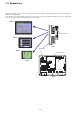
1-4 System Composition The following illustration shows the system composition of @E.Terminal for MC. PLC/general purpose computer Ethernet/RS-232C or RS-485 LAN/CN1/MJ1/MJ2 USB-B SX bus Up to 8 servos and I/O terminals each can be connected. MJ1/MJ2 "V-CP" Screen editor "V-SFT-5" (V5.3.0.0 or later) External PG (only No. 1 axis) @E.Terminal for MC FALDIC ALPHA5 FALDIC - α [No. 1 axis] SX bus station No.: "201" "NW0H-CNV + NW0H-CA3" or commercially available USB cable [No.
Section 2 Specifications Page 2-1 Specifications .............................................................................................................. 2-1 2-1-1 General specifications ........................................................................................................... 2-1 2-1-2 Display unit specifications ..................................................................................................... 2-2 (1) Display unit specifications ..................................
Section 2 Specifications 2-1 Specifications 2-1-1 General specifications Items Physical Operational ambient environmental temperature conditions Storage ambient temperature Operational ambient humidity Operational altitude Operational atmosphere Mechanical working conditions Electrical working conditions Power supply Pollution degree Vibration resistance Shock resistance Noise resistance Static electricity discharge resistance Rated input voltage Rated voltage (tolerance) Permissible momentary power fai
2-1 Specifications 2-1-2 Display unit specifications (1) Display unit specifications Item Display device Display size Colors Display resolution (W x H) Dot pitch (W x H) Backlight Backlight life (average life of backlight only) Backlight auto OFF function Brightness adjustment Surface sheet material POWER lamp NP5M0101-5H4 NP5M0101-4H4 NP5M0101-3H4 NP5N0011-5H4 NP5N0011-4H4 NP5N0011-3H4 TFT color 12.1-inch 10.4-inch 8.4-inch 65,536 colors (without blinks) / 32,768 colors (with blinks) 800 x 600 dots 0.
2-1 Specifications (4) Interface specifications Modular jack 8-pin (MJ1/MJ2) Applications Applicable standards Applications Applicable standards Baud rate Applications Applicable standards Baud rate Applications Applicable standards Baud rate Recommended cable Applications USB-B USB connector (USB-A/B) Applicable standards Synchronization Data length Parity Stop bit Baud rate USB-A Item D-sub 9-pin (CN1) Ethernet port 100BASE-TX/ 10BASE-T (LAN) CF card interface Extensional communication port (CN5
2-1 Specifications (6) Drawing environment Item Drawing method Drawing tool Specifications Exclusive configuration software Name of exclusive configuration software: V-SFT-5 Personal computer: Pentium III 800 MHz or above (Pentium IV 2.0 GHz or above recommended) OS: Windows98SE/NT4.0/Me/2000/XP/XP64 Edition/Vista 32-bit Capacity of hard disk required: Free space of approx.
2-1 Specifications (8) Function performance specifications Item Specifications Screens Screen memory Switch Switch actions Max. 1024 Flash memory: Approx. 12.5 Mbytes (Varies depending on the font) 1024 per screen Set, reset, momentary, alternate, to light (Possible to press a function switch and a switch on the display at the same time) Reverse, blink, exchange of graphics 1024 per screen Pie, bar, panel meter and closed area graph:No limitation Statistics and trend graphs: Max.
2-1 Specifications 2-1-3 Controller unit specifications (1) Application performance specifications Item Specifications Type NP5M0101-5H4/4H4/3H4 Control system Stored program, Cyclic scanning system (default task), periodic task, event task NP5N0011-5H4/4H4/3H4 Input / Output connection method Direct input / output (SX bus) I/O control system Via SX bus: Synchronous refresh with takt CPU 32-bit RISC processor Memory types Program memory, data memory, temporary memory Programming language
2-1 Specifications (2) Specific system memory The table below lists system memory specific to @E.Terminal controller unit. [Expansion annunciator relay area] Address SM1240 (%MX10.124.0) Names Display unit connection status flag Descriptions Represents whether a display unit is connected (ON/OFF of display unit power supply). 1: Connected 0: None [Cause of memory error] Address SM84 (%MX10.8.
2-2 Dimensions and Panel Cut-out 2-2-1 External dimensions and panel cut-out dimensions for the NP5M0101-5H4/NP5N0011-5H4 (Unit: mm) • Front view 313.0 +0.5 -0 246.2 259.6 +0.5 -0 326.4 F1 F2 F3 F4 F5 F6 Panel cut-out dimensions F7 SYSTEM • Side view • Rear view 99.0 (66) 312.0 7.0 CN7 CN5 ONL ERR UROM RUN ALM BAT SX-BUS IN 4:RUN 3:U-TERM 2:TERM 1:STOP 245.2 CPU No. OUT Note) + 24V DC FG CF USER ROM CARD USB LOADER MJ1 MJ2 CN1 LAN U-B U-A • Bottom view 99.0 312.
2-2 Dimensions and Panel Cut-out 2-2-2 External dimensions and panel cut-out dimensions for the NP5M0101-4H4/NP5N0011-4H4 (Unit: mm) • Front view 303.8 289.0 +0.5 -0 +0.5 -0 SYSTEM F1 216.2 231.0 F2 F3 F4 Panel cut-out dimensions F5 F6 F7 • Side view • Rear view (66) 288.0 99.0 7.0 CN7 CN5 ONL ERR UROM RUN ALM BAT SX-BUS IN 215.2 4:RUN 3:U-TERM 2:TERM 1:STOP CPU No. OUT Note) + 24V DC FG CF USER ROM CARD USB LOADER MJ1 CN1 LAN U-B U-A 288.0 99.
2-2 Dimensions and Panel Cut-out 2-2-3 External dimensions and panel cut-out dimensions for the NP5M0101-3H4/NP5N0011-3H4 (Unit: mm) • Front view 220.5 +0.5 -0 165.5 178.0 +0.5 -0 233.0 Panel cut-out dimensions • Side view • Rear view (66) 220.0 96.0 6.9 CF 165.0 CN7 ONL ERR UROM RUN ALM BAT SX-BUS IN 4:RUN 3:U-TERM 2:TERM 1:STOP CN5 CPU No. OUT Note) + 24V DC - 24VDC FG FG USER ROM CARD USB CN1 LAN U-B U-A LOADER MJ1 220.0 96.
2-3 Names and Functions 2-3-1 Display unit (1) NP5M0101-5H4/NP5N0011-5H4 4) 1) 6) 8) 5) CN7 CN5 7) CF 2) MJ1 F1 F2 F3 F4 F5 F6 CN1 MJ2 LAN U-B U-A F7 SYSTEM 16) 3) 9) 10) 11) 12) 13) 14) 15) 17) (2) NP5M0101-4H4/NP5N0011-4H4 1) 4) 6) 8) 5) CN7 CN5 SYSTEM F1 F2 F3 3) F4 CF 2) F5 7) F6 MJ1 F7 9) MJ2 CN1 U-B U-A 10) 11) 12) 13) 14) 15) 17) 2-11 LAN 16)
2-3 Names and Functions (3) NP5M0101-3H4/NP5N0011-3H4 1) 4) 6) 5) CF CN7 3) 7) CN5 2) 24VDC FG CN1 LAN U-B MJ1 9) 12) U-A MJ2 16) 8) 13) 14) 15) 10) 11) 17) 1) Display This is the display unit. 2) Power lamp (POWER) Illuminates in green when the display unit is powered on, and is operating normally. Flashes when an error occurs to the backlight (burned-out backlight, etc.).
2-3 Names and Functions 9) Power supply terminal block (display unit) Supplies the power to the display unit (24 V DC). 10) Modular jack 1 (MJ1) Used for screen data transfer and connection with PLCs or other peripheral devices. 11) Modular jack 2 (MJ2) Used for connection with PLCs or other peripheral devices. 12) PLC communication connector (CN1) Used for connection with a controller (PLC, temperature controller, inverter, etc.). 13) 100BASE-TX/10BASE-T connector (LAN) Used for Ethernet connection.
2-3 Names and Functions 2-3-2 Controller unit Name plate Seal of the occasion of next battery replacement 4) Data backup battery 1) Status indication LED 2) Key switch 5) SX bus connector ONL ERR UROM RUN ALM BAT SX-BUS IN 3) CPU No. selection key switch 4:RUN 3:U-TERM 2:TERM 1:STOP CPU No. 6) Power supply terminal block (3 poles) OUT 9) USB-miniB connector + 24V DC FG USER ROM CARD Version No.
2-3 Names and Functions 1) Status indication LED (Controller unit) Symbol Color Descriptions ONL ERR Green Red Status of the controller unit. ONL ERR Status of controller unit OFF OFF Power OFF, system resetting or initializing Blinks - SX bus standing on ON OFF Normally running ON ON Nonfatal fault, at a running OFF ON Fatal fault at a stop UROM Green Lights on continuously when the CPU recognizes a user ROM card.
2-4 Serial Connector Communication (RS-232C, RS-422/485) with a controller is enabled via the serial connector (CN1). • For NP5M0101-5H4/4H4 NP5N0011-5H4/4H4 • For NP5M0101-3H4 NP5N0011-3H4 Bottom view Bottom view The serial connector pins correspond to signals as given below.
2-5 Modular Jack (MJ1 / MJ2) A screen data transfer cable (MJ1 only), temperature controller, barcode reader, CREC, or V-I/O can be connected to the modular jack (MJ1 or MJ2). • For NP5M0101-3H4 NP5N0011-3H4 • For NP5M0101-5H4/4H4 NP5N0011-5H4/4H4 Bottom view Bottom view Pins of MJ1 and MJ2 correspond to signals as given below. MJ1/2 8 7 6 5 4 3 2 1 Pin No.
2-6 Dip Switches In NP5M0101-5H4/4H4, NP5N0011-5H4/4H4, the dip switch is hidden by the controller unit. Operate the dip switch by detaching the controller unit. The @E.Terminal is equipped with eight (1 to 8) dip switches. When setting the dip switch, turn the power off. Upon delivery, all the dip switches are set to OFF.
2-6 Dip Switches Dip switch number 2 (CF Card interface cover access control) Caution When the dip switch number 2 is set to the ON position, access to the CF card is possible whether the cover is opened or not. In case access to the CF card is disabled because of damage of the CF card interface cover, set the dip switch number 2 to the ON position. Normally keep it in the OFF position. With the dip switch number 2, the LED status when the CF card interface cover is opened can be set.
Section 3 Installation Page 3-1 Mounting Procedure ................................................................................................... 3-1 (1) Mounting procedure ................................................................................................................................ 3-1 (2) Mounting angle ....................................................................................................................................... 3-1 3-2 Power Supply Cable Wiring ..........
Section 3 Installation 3-1 Mounting Procedure (1) Mounting procedure 1) Insert the @E.Terminal unit into the mounting panel (max. thick: 5 mm). Panel cut-out dimensions Types X Unit: mm X Y NP5M0101-5H4/NP5N0011-5H4 313.0 +0.5 -0 246.2 +0.5 -0 NP5M0101-4H4/NP5N0011-4H4 289.0 +0.5 -0 216.2 +0.5 -0 NP5M0101-3H4/NP5N0011-3H4 220.5 +0.5 -0 165.5 +0.5 -0 Y X Y 2) Insert four fixtures attached to the @E.Terminal unit into the mounting holes, and tighten them with the tightening screws.
3-2 Power Supply Cable Wiring Electric shock hazard. Warning Shut the power off before wiring the power supply cable. (1) Power supply cable wiring Power supply terminal blocks of the display unit and the controller unit are connected with each other with a cable by default. Use one power supply terminal block to connect the power supply cable. • For NP5M0101-5H4/4H4 NP5N0011-5H4/4H4 • For NP5M0101-3H4 NP5N0011-3H4 Connect the power supply cable to the power supply terminal block of the display unit.
3-2 Power Supply Cable Wiring • Tighten terminal screws on the power supply terminal block of the display unit with the following torque. Use a power supply cable within the range shown below. Tterminal screw Types NP5M0101-5H4 NP5M0101-4H4 NP5N0011-5H4 NP5N0011-4H4 Screw size Tightening torque φ 3.7mm 3.7mm M3.5 0.8N· m 8mm or less M3.5 1.2N· m AWG18 - 16 8mm or less φ 3.7mm 3.7mm NP5M0101-3H4 NP5N0011-3H4 Power Cable Crimp-style terminal 7.1mm or less AWG16 - 14 7.
3-2 Power Supply Cable Wiring (2) Grounding Caution Be sure to establish a ground of the @E.Terminal. (The level of grounding resistance should be less than 100Ω.) • An independent earth pole must be used for the @E.Terminal. • Use a cable which has a nominal cross section of more than 2 mm2 for grounding. • Set the grounding point near the @E.Terminal to shorten the distance of grounding cables. @E.Terminal Other equipment @E.Terminal Other equipment @E.Terminal Other equipment * When the @E.
Section 4 Inspection and Maintenance Page 4-1 Inspection and Maintenance ...................................................................................... 4-1 4-1-1 Daily inspection ..................................................................................................................... 4-1 4-1-2 Periodical inspection ............................................................................................................. 4-1 4-2 Battery Replacement ...................................
Section 4 Inspection and Maintenance 4-1 Inspection and Maintenance Be sure to turn off the power before conducting inspection or maintenance. Warning Failure to do so could cause an electric shock or damage to the unit. 4-1-1 Daily inspection • • • • Check that the screws on the @E.Terminal are tightened firmly. Check that the connectors and terminal screws used for connection with other devices are tightened firmly.
Battery replacement 4-2 Battery Replacement When the time comes to replacement the battery, replace it for a new one even if battery error is not displayed. Also, when low battery voltage of the display unit and the controller unit is discovered, replace the battery for a new one immediately. Replacement the batteries of the display unit and the controller unit at the same time.
Battery replacement 4-2 Battery Replacement • Battery replacement of display unit 1) Remove the controller unit from @E.Terminal. Remove mounting screws at three places to remove the controller unit from the display unit. Be careful not to drop or lose the mounting screws. CN7 CN5 ONL ERR UROM RUN ALM BAT SX-BUS IN 4:RUN 3:U-TERM 2:TERM 1:STOP Mounting screws at three places M3 screws thread, Tightening torque: 0.5 to 0.7N·m CPU No.
Maintenance services 4-3 Maintenance Services 4-3-1 Ordering notes When ordering electrical and control equipment (or requesting price estimates), the following general notes are to be observed, unless otherwise specified in the estimation paper, contract paper, catalogs, or specifications. When the product is delivered, check the contents of the package as soon as possible. Even before inspection, use caution on storing and using the product safely.
Appendix 1 About Project for @E.Terminal (No contents installed) Page Appendix 1 About Project for @E.Terminal (No contents installed) .................... App.
Appendix 1 About Project for @E.Terminal (No contents installed) When you make new project for controller of @E.Terminal (No contents installed) by personal computer loader (SXprogrammer Expert/ Standard), download template for new project from our homepage. The project for controller of @E. Terminal for MC is stored in backup CD. (1) Download template Access to our homepage, download from [Software libraries] of [Programmable controllers]. (Address: http://www.fesys.co.
Gate City Ohsaki, East Tower, 11-2, Osaki 1-chome, Shinagawa-ku, Tokyo, 141-0032,Japan Phone: +81-3-5435-7280 Fax: +81-3-5435-7425 URL http://www.fesys.co.jp/eng/ Printed on recycled paper.