
Network Card User's Manual


3-1
Section 3 Installation
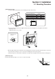
3-1 Mounting Procedure
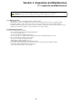
(1) Mounting procedure
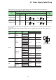
1) Insert the @E.Terminal unit into the mounting panel (max. thick: 5 mm).
X
Y
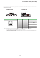
NP5M0101-5H4/NP5N0011-5H4
NP5M0101-3H4/NP5N0011-3H4
NP5M0101-4H4/NP5N0011-4H4
X
Y
313.0
289.0
220.5
X
246.2
216.2
165.5
Y
Panel cut-out dimensions
Types
Unit: mm
+0.5
-0
+0.5
-0
+0.5
-0
+0.5
-0
+0.5
-0
+0.5
-0
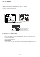
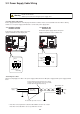
2) Insert four fixtures attached to the @E.Terminal unit into the mounting holes, and tighten them with the
tightening screws.
Tightening torque: 0.5 to 0.7 N·m
C
N
7
C
N
5
C
F
L
A
N
U
-
B
U
-
A
R
E
S
E
T
C
N
1
M
J
2
M
J
1
4
:
R
U
N
3
:
U
-
T
E
R
M
2
:
T
E
R
M
1
:
S
T
O
P
O
N
L
E
R
R
U
R
O
M
R
U
N
A
L
M
B
A
T
D
C
2
4
V
N
o
.
U
S
B
L
O
A
D
E
R
U
S
E
R
R
O
M
C
A
R
D
0
V
F
G
C
P
U
S
X
-
B
U
S
I
N
O
U
T
17.8
10.5
Fixture dimensions
(Unit: mm)
18.0
* When the @E.Terminal unit is attached to the mounting panel, the fixtures and frame grounds (FG) are connected.
To prevent static electricity, be sure to connect the mounting panel to the frame ground.
3) Mount the gasket so that it will be sandwiched securely between the @E.Terminal unit and the mounting panel.
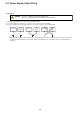
(2) Mounting angle
Install the unit within the angle of 15° to 135° as shown on the right.
0°
135°
90°
15°
Display
Display