Back OPERATOR'S MANUAL GMDSS Radio Station Model RC-1800F/1800T This manual covers the general description of the GMDSS Radio Station. Refer to the separate manuals for detailed information on individual units mounted in the console. www.furuno.
i
TABLE OF CONTENTS Chapter 1 INTRODUCTION 1.1 Operational Overview ....................................................................................... 1-1 1.2 System Diagram ............................................................................................... 1-2 1.3 Equipment. Description..................................................................................... 1-3 1.4 Mutual Operation of Equipment ........................................................................ 1-4 1.
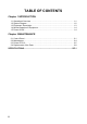
Chapter 1 INTRODUCTION 1.1 Operational Overview The RC-1800F/1800T radio rack console conforms to the IMO regulations for GMDSS radio equipment. It contains an SSB radiotelephone, DSC terminal, NBDP terminal and Inmarsat C mobile earth station. The RC-1800F is operated with the control panel and the dimmer knob. You can monitor the AC mains source by the Lamp. Power can be checked with the power meter. The RC-1800T is operated with the control panel and the dimmer knob (option).
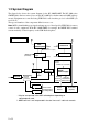
1.2 System Diagram The figure below shows the system diagram for the RC-1800F/1800T. The RC-1800 series GMDSS Radio Station consists of two models' RC-1800F (floor deck mount) and 1800T (tabletop mount). Equipment are controlled using FURUNO’s radio interface protocol called MIF (see note below). The type and number of the component differ from set to set. Note: MIF is a handshaking type signal exchange protocol developed by FURUNO for remote control of radio equipment.
1.3 Equipment Description Regulations require that all equipment be powered while the vessel is underway. SSB Radiotelephone For ship-ship and ship-station radio communications in the MF/HF band (1.6-26.
1.4 Mutual Operation of Equipment As noted earlier, the equipment in this radio console are interfaced by FURUNO's MIF radio interface. For example, to transmit a message over the MF/HF DSC Terminal or NBDP Terminal, the Tx and Rx frequencies and class of emission are automatically set on the SSB Radiotelephone and then the message is transmitted. Two printers are supplied and one is dedicated to the Inmarsat C.
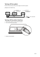
Turning off the system Reverse the order shown at the previous page to turn off the system. (Example for RC-1800F-15A) Battery Charger Inmarsat C (24 VDC backed up by battery) FS-1570 (24 VDC backed up by battery) PR-850AR PR-300 24 VDC Battery 100/110/220 VAC (Main Switch) Turning off the printer interface 1. Remove four screws to remove the control panel. 2. Turn off the switch shown below. IF8 I 500 ON OF F 3. Attach the control panel.
This page is intentionally left blank.
Chapter 2 MAINTENANCE 2.1 Control Panel The figure which follows is an exploded view of the Control Panel. 4 3 STOP 5 BUZZER switch Dimmer knob: right side of console (refer to page 1-1) (RC-1800T: option) Voltmeter and Ammeter 2 EMG LIGHT 1 switch BATTERY MONITOR lamp 6 BATTERY CHARGER switch For flooded lead-acid battery: Control description 1. EMG LIGHT switch Turns the emergency lamps at the top of the console on/off (RC-1800T: option).
2. BATTERY MONITOR lamp IN USE lamp (AC power failure: orange) Lights to alert that the AC power has failed and the radio equipment is being powered by the radio battery (DC power) alone. When lit, only the equipment related to distress communication are powered. (Power is not supplied to console lights.) LOW VOLT lamp (low battery voltage: red) Lights to alert that the battery voltage is below 22 VDC. (The aural alarm sounds until the voltage becomes higher than 22 VDC.) 3.
2) Confirming charging Confirm that the BATTERY CHARGER switch on the Control Panel is set to AUTO. Further, confirm that the voltage shown on the battery voltage meter on the Control Panel is normal (between 26.5 VDC and 27.0 VDC). 3) Cleaning The battery and the area around it should always be clean and dry. Clean the battery case with a water-moistened cloth. Do not use organic solvents, thinner, gasoline, benzine or alcohol to clean the battery. (They may crack the case.
WARNING Keep sparks and lit smoking materials away from the lead-acid battery. Make sure the battery room is well ventilated. The battery emits hydrogen gas which can cause explosion. The electrolyte in the lead-acid battery contains sulfuric acid, which can be harmful to the human body, particularly to the eyes. If sulfuric acid contacts eyes, skin or clothing, flush directly with water. For eyes, contact a physician. Loss of eyesight can result.
2. Cleaning floppy disk drives The heads in the floppy disk drive of the terminal unit and Inmarsat-C should be cleaned regularly to prevent damage to floppy disks. Use a cleaning floppy disk. (FURUNO can supply a cleaning floppy disk. It is type MCD-2, code no. 000-116-420.) Procedure 1. Insert ∞a cleaning floppy disk in the drive. 2. Execute “Format” operation (in the F1 menu). The access lamp on the drive lights. 3. Wait until the access lamp goes off. Remove the disk.
Loading roll paper This section shows you to load the roll paper. CAUTION Keep fingers away from edges on the printer and cover. Edges can cut fingers. Observe the following cautions when loading the paper: • To prevent paper skewing or jamming, be sure the paper is positioned correctly. • Never turn the platen knob too fast—gears may be damaged.
Removing remaining paper 1. Press P. PARK the switch to back up the paper. Turn off the power. 2. Unfasten screws A and push back B (for both right and left) shown below to remove the printer cover. C Paper Paper Cover Screw A B Printer cover 3. Swing out the paper cover by 100° to 120° then lift it from the right-hand side to remove it from the printer. 4. Referring to the figure above, lift the paper bail C.
6. Pull the paper bail forward. Manually feed the paper over the paper guide bar and under the platen. Turn the platen knob clockwise to feed the paper so it reaches the paper guide bar. Paper Guide Bar Paper Release Lever Platen Knob Paper Bail Platen 7. Unlock the paper release lever to adjust the paper and then lock it. 8. Slide the left and right guide rings to position the paper straightly. Guide Ring Guide Ring 9. Replace the paper cover, the printer cover and roll paper stay.
SPECIFICATIONS OF THE GMDSS RADIO STATION RC-1800-F/T 1 RACK CONFIGURATION 1.1 SSB Radiotelephone: FS-1570 (150 W), FS-2570 (250 W), FS-5000 (400 W) 1.2 MF/HF DSC/Watch Receiver: DSC-60 1.3 NBDP Terminal: DP-6 Note) NBDP terminal is not incorporated in the dual Inmarsat C radio rack console. 1.4 Inmarsat C MES: FELCOM 15 1.5 Printer PP-510 (2 sets) 1.
SPECIFICATIONS OF THE SSB RADIOTELEPHONE FS-5000 1. GENERAL (1) Communication System (2) Frequency Range Full-duplex, Semi-duplex or simplex Transmit: 1.6065 MHz to 29.9999 MHz (100 Hz steps) Receive: 0.1 MHz to 29.
(7) Audio Output Internal speaker: 2 W/ 8 ohms External speaker: 4 W/ 4 ohms Line output: (8) Standard Features 0 dBm/ 600 ohms Scan, Sweep, Noise Blanker, Voice-activated Squelch 4. ANTENNA COUPLER (1) Tuning System CPU controlled fully automatic tuning system (2) Frequency Range 1.6 MHz to 27.5 MHz (3) Input Impedance 50 ohms (viewed from transceiver) (4) Antenna 7 m to 18 m wire or whip antenna + wire (5) Tuning Power 10 W (6) VSWR less than 1.5 (7) Tuning Time 0.
SPECIFICATIONS OF THE DSC/WATCH RECEIVER DSC-60 1. DSC TERMINAL (1) Line out 0 dBm (adjustable between -12dBm and +12dBm), 600 ohms, balanced (2) Line in -30 to +10 dBm, 600 ohms, balanced (3) Frequency shift Mark: 1615 Hz, Space: 1785 Hz (4) Baud rate 100 baud’s ± 30 x 10-6 (5) Protocol Complies with ITU-R Rec.493-9, 541-8, 1082-1 2. DSC WATCH KEEPING RECEIVER (1) Receiving Frequency For MF spec: 2187.5 kHz For MF/HF spec: 2187.5 kHz, 4207.5 kHz, 6312 kHz, 8414.5 kHz, 12577 kHz and 16804.
4. MF/HF SSB TRANSCEIVER REMOTE STATION (1) Line out: 0 dBm, 600 ohms, balanced (2) Line in: 0 dBm, 600 ohms, balanced (3) AF input (Microphone): -46 dBm, 600 ohms, unbalanced (4) AF output (Loudspeaker): 3 W, 4 ohms (Handset): 1 mW, 200 ohms 5. DISPLAY (1) LCD Unit: 120 x 64 dots (2) Characters 20 characters x 8 lines (1 character: 5 x 7 dot) max. 20 characters x 10 lines (1 character: 5 x 5 dot) max. (3) Back Light: Yellow, 8 tones (4) Contrast: 64 tones 6. I/O DATA (1) Nav.
SPECIFICATIONS OF THE NBDP TERMINAL DP-6 1. COMMUNICATIONS (1) Communication Mode ARQ, FEC, DIRC (FSK) (2) Communication Protocol ITU-R Rec. 625, 476-3, 490, 491, 492 (3) ID Code 4 units, 5 units and 9 units (4) Line Code 4B/3Y fixed mark (International) (5) Modulation AFSK (6) Tone Frequency 1615/1785 Hz (7) Tracking Range ±80Hz (8) Line Input/ Output 0 dBm (-30 dBm to +10 dBm, 600 ohms balanced) 2.
SPECIFICATIONS OF THE PRINTER PP-510 1.
SPECIFICATIONS OF THE AC/DC CHANGE-OVER UNIT (RADIO SWITCH BOX) 1. BATTERY CHARGER (BC-6158) (1) Applicable Battery 200AH Normal ship battery (2) Power Source 100/110/200/220 VAC, 1 phase, 50/60 Hz (3) Output for Battery 28 VDC, 30 A nominal (4) Charge/discharge Meter built in the radio console panel (5) Control Panel built in the radio console 2.
SPECIFICATIONS OF SSB RADIOTELEPHONE FS-1570/2570 1 MF/HF DIGITAL RADIOTELEPHONE 1.1 GENERAL 1.1.1 Communication System Semi-duplex or simplex 1.1.2 Class of Emission J3E: Telephone J2B (F1B): DSC and NBDP H3E: reception only 1.1.3 Frequency Range 100.00 kHz to 29,999.99 kHz 1.1.4 Number of Channel User programmable: 255 TX/RX pairs All ITU channels incorporated (include DSC/NBDP channels) 2182 kHz (single action) 1.1.5 Display Method Monochrome LCD (120 x 64 dots) 1.1.6 Backlight 8 tones 1.1.
1.6 Inter-modulation Better than 80 dBµV 1.7 Spurious Response Better than 70 dB 1.8 AGC SLOW/FAST/OFF 1.9 BFO Frequency Telex/DSC: 1,700 Hz, Facsimile: 1,900 Hz 1.10 Audio Output Power Internal speaker: 1W/ 8 ohms External speaker: 4W/ 4 ohms Handset: 2.5mW/ 150 ohms Line output: 0 dBm/ 600 ohms 1.11 Standard Features Noise Blanker, Voice-activated squelch, Pre-selector 2 DSC/WATCH KEEPING RECEIVER 2.1 DIGITAL SELECTIVE CALLING 2.1.1 Frequency Shift Space: 1785.0 ± 0.5 Hz, Mark: 1615.0 ± 0.
2.3.5 Frequency Stability within ±10 Hz 2.3.6 Intermediate Frequency 1st: 54,455 kHz, 2nd: 455 kHz 2.3.7 Selectivity -6 dB: 270 Hz to 300 Hz, -30 dB: within ± 380 Hz, -60 dB: within ±550 Hz 2.3.8 Receiving System Double-conversion superheterodyne 2.3.9 Radiation within 2 nW 2.3.10 RX Error Rate 1 % or less at 1 µV input voltage 2.3.11 Spurious Response 31.6 mV non-modulated at 10µV input voltage, at error rate within 1% 2.3.12 Scanning Reception max. 6 frequencies within 2 s (MF/HF) 2.
5 ANTENNA COUPLER 5.1 Tuning System 5.2 Frequency Range 5.3 Input Impedance 5.4 Antenna 5.5 Power Capability 5.6 VSWR 5.7 Tuning Speed 5.8 Dummy Load CPU controlled fully automatic tuning system 1.6 MHz to 27.5Hz 50 ohms 7m to 30m wire or whip antenna 150 W (FS-1570), 250 W (FS-2570) 1.5 max Within 15 s FS-1570: 10 ohms + 250 pF/100W mounted in coupler FS-2570: 10 ohms + 250 pF/200W mounted in coupler 6 INTERFACE 6.
SPECIFICATIONS OF INMARSAT C MES FELCOM 15 1 GENERAL 1.1 Transmitting Frequency 1626.5 to 1646.5 MHz 1.2 Receiving Frequency 1530.0 to 1545.0 MHz 1.3 Antenna Omnidirectional 1.4 G/T Better than -23 dB/K (elevation angle 5°) 1.5 EIRP 12 to 16 dBW (elevation angle 5°) 1.6 Modulation BPSK 1.7 Modulation Rate 1200 sps 1.8 Coding Convolution with coding rate 1/2 and constraint length 7 1.9 Decoding Viterbi decoder 1.10 Transmission Speed 600 bps 1.
The paper used in this manual is elemental chlorine free. ・FURUNO Authorized Distributor/Dealer 9-52 Ashihara-cho, Nishinomiya, 662-8580, JAPAN All rights reserved. Printed in Japan A : FEB . 2001 K : DEC . 05, 2012 Pub. No.