
Operator`s manual


1 – 2
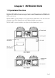
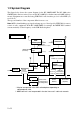
1.2 System Diagram
The figure below shows the system diagram for the RC-1800F/1800T. The RC-1800 series
GMDSS Radio Station consists of two models' RC-1800F (floor deck mount) and 1800T (tabletop
mount). Equipment are controlled using FURUNO’s radio interface protocol called MIF (see
note below).
The type and number of the component differ from set to set.
Note: MIF is a handshaking type signal exchange protocol developed by FURUNO for remote
control of radio equipment. In the RC-1800F/1800T, for example, the MF/HF DSC terminal
can automatically set the frequency on the SSB Radiotelephone.
100/110/
220/440VAC
(Main Source)
SSB
Radiotelephone
Distribution
PCB
24VDC
24VDC
24VDC
24VDC
24VDC
NMEA OUT
(Maximum five outputs)
(Inside Console)
(Inside Console)
DSC
Terminal*
NBDP
Terminal**
IF-8500
(Printer
Interface)
PP-510
PP-510
(Printer)
(Printer)
No.1
No.2
FM-8500
FM-8500
NMEA IN
(Nav data)
24VDC (To each unit)
RC-1800F only, built in
console
AC/DC
Power Supply
24VDC
24VDC
(Reverse
Source)
Alarm Unit
(Option)
Radio
Battery
Inmarsat-C
(Distress Alert Unit)
External VHF
Radiotelephone
(Including DSC)
RC-1800F/1800T
*: May be incorporated in the SSB radiotelephone depending on
radiotelephone used.
**: NBDP terminal is not incorporated in the dual Inmarsat C radio rack console.