Ericsson G32 / G36 Fixed Wireless Terminal for GSM/EDGE Mobile Networks User Guide E
EN/LZT 151 235 R1B © Ericsson AB 2006 – All Rights Reserved
Table of Contents Table of Contents .........................................3 Welcome ......................................................4 Fixed Wireless Terminal ................................6 Installation ....................................................9 Connecting Devices to the FWT..................16 Advanced Features.....................................24 PC Data Configurations ..............................34 Web-based Configuration ...........................55 Troubleshooting...........
Welcome Welcome to the User Guide for the G32 / G36 Fixed Wireless Terminal. Important information: Some of the services described in this guide might not be supported by all networks. Please, contact your network operator for information on different network services operational in your GSM network. The latest version of this user guide can be downloaded from: http://www.ericsson.com/enterprise/library/manual.shtml Disposal of the product Your product should not be placed in municipal waste.
Copyright No part of this document may be reproduced without the written permission of the copyright owner. The contents of this document are subject to revision without notice due to continued progress in methodology, design and manufacturing. Ericsson shall have no liability for any error or damage of any kind resulting from the use of this document.
Fixed Wireless Terminal Product Description The FWT is a flexible and cost-effective solution for connection to the wireless GSM network when there is no fixed line infrastructure or if you need additional telephone lines. The G36 can also be connected to a PBX so you can benefit from the Least Cost Routing (LCR) capabilities offered by most PBX vendors to optimize your costs by routing outgoing calls to mobile phones through the GSM network.
Supplied Parts After unpacking, please check that the following parts and list of components are included: List of Components 1. FWT unit 2. Antenna 3. 4 x mounting screws 4. Power cable (USA, UK, EU or AUS) 5. AC/DC adapter 6. Wall mount bracket 7. Telephone cable 8. Quick Guide and User Guide manuals 9.
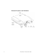
External Connector and Indicators 8 Fixed Wireless Terminal: G32 & G36
Installation SIM Card Your network operator provides you with a SIM (Subscriber Identity Module) card. The SIM card contains information about your telephone number and the services included in your subscription. Preparing Your FWT You need to follow these steps before you install the FWT on the wall and finalize all connections. Warning: The FWT should be switched off before inserting or removing your SIM card or connecting any devices to the FWT. Assembly 1. Connect the antenna.
2. Remove the front cover, by pressing down and pushing the small tab that is in the center of the bottom part of the FWT. Open the SIM Card holder and insert the SIM Card. 3. Close the SIM Card holder, placing it horizontally and securing it with the sliding part of the holder. 4. Install the battery (optional) in the battery compartment (over the SIM Card). To do so, connect the battery cable to the FWT connector.
Switch on the FWT Connect the power supply. The FWT switches on automatically and the LED indicators start flashing. Note: If the Power LED is off, there is a problem with the power supply. Please refer to the topic Troubleshooting documented on page 61 for more detailed information. Enter PIN Most SIM cards are protected with a PIN (Personal Identity Number), which you get from your network operator and which you need in order to access the network.
2. Check that your computer has the standard modem installed, if not add one by following the steps described in PC Data Configurations on page 34. 3. Open your Web Browser on your PC, and type in the following URL: http://192.168.1.1/pin.asp 4. The following screen will be displayed. 5. Type in your PIN and then click on the Submit button. If the PIN is entered incorrectly three times, the SIM card will be blocked.
Now you have prepared the FWT for wall installation. Please, follow the instructions below for complete wall installation. Installing the FWT on the Wall FWT Location The GSM signal strength available at the FWT location affects the performance of the unit. The stronger the GSM signal, the better the FWT performance. Tip: Test several potential locations by moving the FWT while looking at the Radio LED.
Wall mounting Please proceed as indicated in the following picture. 1. Fix the wall-mounting bracket on the wall. 2. Press the FWT against the wall-mounting bracket. 3. Slide the FWT downwards. Warning: Once you have fixed the FWT to the wall and switched it on, check the final status of the LEDs. If either one is off, then there is a problem with the power supply or the GSM signal.
Now the FWT is ready for connecting devices and making calls. Note: If you want to remove the FWT from the wall bracket, then you have to press the tab (step 1) as indicated in the following picture and then slide the FWT upwards (step 2).
Connecting Devices to the FWT Warning: Before you start any connections please refer to the topic Product Care and Safety documented on page 71 for more detailed information and contact your network operator if you have any questions. Warning: To ensure good protection against electrical discharges and the best audio quality, proper grounding of the power supply is strongly recommended.
The FWT is also equipped with a USB port that enables you to use it as a GSM modem. This enables PC fax and for data transfers as well as SMS services. Note: When making the connections, the two-wire telephone cable polarity does not matter. Tip: If your home or company is already wired with telephone cable, you only need to connect the cable to the FWT RJ11 connector and your telephone line will be up and running in all rooms. Note: The telephone wire must be installed indoors.
communication can take place at a time, in the same way as an ordinary fixed line. You cannot, for example, receive or originate a telephone call while sending or receiving a fax. Warning: In order to avoid GSM interferences (noise), place the FWT at least three (3) meters (horizontal) away from electronic devices, including the telephone equipment connected to the FWT, or other household electronic devices such as televisions or radio receivers.
• The trunk card must support either Busy Tone Detection (BTD) or Polarity Reversal Detection on answer and release. • The PBX can be programmed to utilize Least Cost Routing (LCR), if available, to automatically choose the trunk where the G36 FWT is connected. • If the PBX does not offer LCR, choose the trunk where the G36 FWT is connected manually with a special dialed prefix. Check the installation in the same way as before. The G36 FWT is compatible with most analog PBXs on the market.
Routing (LCR) programmed PBX. Once LCR is programmed, make a call to a mobile telephone number. See if the call is established through the FWT and check the speech quality. If the PBX does not offer the LCR option, choose the FWT trunk manually with a specific prefix. Check the installation in the same way as before. If you encounter problems, contact your distributor or network operator.
destination number (B-number) in order to inform the FWT that the next call is a fax call (Example: *01*B-number). This is not usually necessary, as most faxes automatically send the CNG tone so that the fax call is made automatically by the FWT. Receiving a fax Incoming faxes are received in the same way as using a fixed line. Note: If you have a SIM card that does not support separate voice and fax numbers, the FWT does not recognize the type of incoming call.
EDGE/GPRS data access type allows you to make outgoing connections only, usually to connect to the Internet. Your GSM network operator provides you with an Internet connection as part of the EDGE/GPRS service. Warning: The EDGE /GPRS data communication service has to be registered with your network operator. Otherwise, the network will not accept EDGE connections.
Tip: If you already have an Internet connection configured for a fixed line, you do not need to make any changes, just connect your PC to the FWT line (RJ11) instead of a fixed line. Note: If your modem is an old model and it is not able to send the CNG tone, you should include *02* before the destination number (B-number) in order to indicate to the FWT that the call to be made is a data call (Example: *02*B-number).
Advanced Features If a DTMF telephone is connected to the FWT, the following features can be accessed. Changing Volume During a call, you can increase or decrease the reception volume level. • Increase volume: dial R#### • Decrease volume: dial R**** Call Divert You can divert incoming calls to another phone number when you are unable to answer. The following table shows the divert alternatives as well as the way to proceed to manage this function.
To manage diversion of calls ... With function ... Dial ... You will hear ...
To manage restrictions of calls ... With function ... Dial ... You will hear ...
Call waiting service If you wish to be able to receive a second call while another call is in progress, you must turn on the call waiting service. Note: These dialing sequences may vary depending on your network operator. If these do not work, please consult your network operator or check the user guide provided with your subscription. To manage call waiting function ... All outgoing calls With function ... Dial ... You will hear ...
• To put the ongoing call on hold and answer the waiting call: press R2. R2 You can switch again between both calls by pressing R2 each time. Note: If “divert when busy” is on, the waiting call is diverted to the number you have specified. Conference Calls In a conference call, you can have a joint conversation with up to four other participants. To create a conference call • If you are in conversation with participant 1, put it on hold (press R), and dial participant 2.
Phonebook / Abbreviated Dialing You can store telephone numbers in either the SIM card memory or the FWT memory. Up to 99 telephone numbers can be stored in each of them. The following table shows how to manage the phonebook with the 99 memory positions (Pos). Warning: The position must always consist of two digits. For example, memory position number 1 has Pos=01 To manage the phone book in ... With function ... Dial ... You will hear ...
Sending Tone Signals During a call, you can press keys 0-9, * and # to perform interactive services, for example banking by phone or control of an answering machine. Minute Minder If the minute minder is activated, you hear a beep once every minute during a call as a reminder of the duration of the ongoing call. To manage minute minder function ... Dial ... Activate **42*1# 1 beep Deactivate #42*1# 3 beeps Check status *#42*1# 1 beep if activated 3 beeps if deactivated You will hear ...
To manage alternate line service function ... Dial ... You will hear ... Activate Line 1 **591# 1 beep Activate Line 2 #592# 3 beeps Check status Line 1 *#591# 1 beep if activated 3 beeps if deactivated Check status Line 2 *#592# 1 beep if activated 3 beeps if deactivated Note: If instead of hearing beeps you hear a deep tone, this means that there has been an error in the activation or deactivation. SIM Card Security To Manage your SIM Card Most SIM cards are locked at the time of purchase.
Alternatively, use the Web interface. Please follow these steps before you enter your PUK code: • Open your Web Browser on your PC, and type in the following URL: http://192.168.1.1/puk.asp • The following screen will be displayed: • • • • Type the new value in the PIN1 field. Type in PIN1 new value confirmed. Type in your PUK code. Then click on the Submit button.
Alternatively, use the Web interface. Please follow these steps before you enter your PUK code: • Open your Web Browser on your PC, and type in the following URL: http://192.168.1.1/puk.asp • The following screen will be displayed: • • • • Type the new value in the PIN1 field. Type in PIN1 new value confirmed. Type in your PUK code. Then click on the Submit button.
PC Data Configurations USB Driver Installation The Windows™ operating system requires an upgraded USB driver to allow access to the FWT.
• Once the driver is installed successfully, connect the FWT to the USB port to complete the installation. • Select the option “No, not this time” and click on Next.
• Select the option “Install the software automatically” and then proceed to the next screen. • If this warning screen appears, click on “Continue Anyway”. • Click on Finish.
• Now the modem for the FWT needs to be installed. Windows will automatically display the following screen.
• Select the option “Install from a list or specific location” and proceed to the next screen. • If this warning screen appears, click on “Continue Anyway”.
Windows™ XP EDGE/GPRS set-up Warning: This instruction can differ depending on which Windows™ version and service pack is installed on the PC. It’s necessary to choose Windows™ standard modem on an available USB port (56000 bps V.90 modem). Check that your computer has the standard modem installed, if not add one in Phone and Modem Options. To configure your EDGE/GPRS connection for a PC with Windows™ XP operating system, follow the provided steps: 1. Click on the Start button. 2.
6. With the Network Connection Type screen displayed, select the Connect to the Internet option and click on the Next button 7. With the Getting Ready screen displayed, select the Set up my connection manually option and click on the Next button.
8. With the Internet Connection screen displayed, select the Connect using a dialdial- up modem option and click on the Next button. 9. With the Connection Name screen displayed, type the ISP Name you require in the ISP Name field and click on the Next button.
10. With the Phone Number to Dial screen displayed, type the phone number you will use during the dial up process in the Phone number field. Click on the Next button. Note: To access the web-based configuration pages on the FWT enter the phone number *98*06#. 11. With the Connection Availability screen displayed, select the Anyone’s use option and click on the Next button.
12. If your operator requires certain Internet account information when you do a dial up, you have to complete all the relevant information on the displayed Internet Account Information screen. Once you have completed all the required information, click on the Next button. 13. With the Completing the New Connection Wizard screen displayed, ensure that you select the Add a shortcut to this connection to my desktop check box option. Click on the Finish button.
You have now successfully configured a new dial up connection using the Windows™ New Connection Wizard. 14. Locate and double-click on the newly created EDGE/GPRS connection icon. 15. With the Connect screen displayed, confirm all the displayed information and click on the Dial button. Note: To access the web-based configuration pages on the FWT enter the phone number *98*06#.
Windows™ 2000 EDGE/GPRS set-up Note: Your PC must have the Remote Access Service and the TCP/IP protocol installed within the network components. You can check this in ‘Start->Settings->Control Panel’ and double clicking on ‘Network’. If not, these components have to be previously added from your Windows™ installation disk. To configure your EDGE/GPRS connection for a PC with Windows™ 2000 as operating system, follow the provided steps: 1.
6. Phone and Modem Options select ‘OK’ to proceed 7. Network Connection Wizard. Click ‘Next’. 8. With the Welcome to the Network Connection Wizard screen displayed, click on the Next button.
9. With the Network Connection Type screen displayed, select the DialDial-up to the Internet option and click on the Next button. 10. With the Welcome to the Internet Connection Wizard screen displayed, select the most appropriate option and click on the Next button.
11. With the Install New Modem screen displayed, select the Don’t detect my modem; I will select it from a list option and click on the Next button. 12. With the Install New Modem screen displayed, select the appropriate modem from the displayed options and click on the Next button.
13. With the Install New Modem screen displayed, select the most appropriate USB port from the displayed list. Click on the Next button. 14. With the Install New Modem screen displayed, click on the Finish button.
Windows™ 2003 EDGE/GPRS set-up Note: Your PC must have the Remote Access Service and the TCP/IP protocol installed within the network components. You can check this using Start: Settings: Control Panel and doubleclicking on the Network icon. If not, these components have to be previously added from your Windows™ installation disk. To configure your EDGE/GPRS connection for a PC with Windows™ 2003 as operating system, follow the steps provided: 1.
5. With the Network Connection Type screen displayed, select the Connect to the Internet option and click on the Next button. 6. With the Internet Connection screen displayed, select the Connect using a dialdial- up modem option and click on the Next button.
7. With the Connection Name screen displayed, type the name of your ISP (Internet Service Provider), and click on the Next button. 8. With the Phone Number to Dial screen displayed, type your ISP’s phone number and click on the Next button. Note: To access the web-based configuration pages on the FWT enter the phone number *98*06#.
9. With the Connection Availability screen displayed, select the Anyone’s use option and click on the Next button. 10. If your operator requires certain Internet account information when you do a dial up, you have to complete all the relevant information on the displayed Internet Account Information screen. Once you have completed all the required information, click on the Next button.
11. With the Completing the New Connection Wizard screen displayed, ensure that you select the Add a shortcut to this connection to my desktop check box option. Click on the Finish button. You have now successfully configured a new dial up connection using the Windows™ New Connection Wizard. 12. Locate and double-click on the newly created EDGE/GPRS connection icon 13. With the Connect screen displayed, confirm all the displayed information and click on the Dial button.
Web-based Configuration This chapter describes the interface and user settings (volume, ringing signals, dial speed setups etc) that are available and the procedures for the use of your PCs standard modem to make data calls (Internet browsing, e-mail, etc.) through the FWT line interface. To be able to send and receive data calls, you need: • A PC equipped with an analog modem and the appropriate computer program (Web Browser, E-mail, etc).
Localization Allows you to change the language in which the web page will be displayed. The options are: • English (default) • Spanish User settings This option will allow you to change the reception volume level from 0 to 3, the default is 1.
Ringing Signals Ring Signal functionality Activation of the ring signal functionality according the following conditions: • • • • • • Disabled for all incoming calls Enabled for all incoming calls Enabled only for voice calls Enabled only for fax calls Enabled only for data calls Enabled only for fax and data calls As default “Enabled, all incoming calls” is selected Ringing signal sequence This provides the possibility of setting different ringing sequences depending on the incoming call’s nature.
Data ringing signal defined sequence Ringing signal used for incoming data call. Calling Line Identification Presentation Selection of Calling Line Identification Presentation (CLIP) functions. Allowed protocols are: • • • • ETSI V.23 ETSI DTMF Bellcore None By default, this functionality is set to the ETSI V.23 protocol.
Abbreviated Dialing This check box option allows a user to Enable/Disable the abbreviated dialing function. By default, this functionality is set to Enabled. Dial Speed Setup This setting allows you to adjust the dialing speed (interval between digits). There are five possibilities. By default, this functionality is set to Normal. Minute minder Indicates if the minute minder is active or not. By default, this functionality is set to Deactivated.
• Bearer capability – the bearer capability associated to a destination number. This bearer capability can be voice, fax or circuit-switched data. Change PIN This section allows you to change your PIN and PIN2. Please refer to the topic To Change your PIN documented on page 31 for more detailed information. IP Address This field allows you to change the default IP address (192.168.1.1) of the FWT.
Troubleshooting This chapter describes the procedures to identify and, if possible, correct problems that might occur with the FWT or its installation. Some problems require that you call your network operator, but most problems you may encounter can be easily corrected.
The Power LED (red and green) indicates the FWT power supply status: Color Power supply situation Green Power supply in ON (AC adapter) Red The FWT is powered from the battery back-up OFF Power is OFF When both LEDs are flashing simultaneously, simultaneously it means that the FWT is under alarm conditions. conditions In this situation, ONLY EMERGENCY CALLS can be made.
LED indicators status If you see… It means… Do this… Power LED Green Radio LED ON or flashing AC power is ON. The FWT is connected to the cellular network and available for use. Normal operation mode Start using your FWT. If Radio LED is flashing, Please refer to the topic FWT Location on page 13. If you are unable to make a call, check the telephone cable connection or the PBX connections and program.
Audible Tones The FWT generates audible tones in your telephone set, thus providing the same service characteristics as the one given by the traditional fixed line network. The following table describes the nature of the main tones you will get when using the unit. Other standard call progress tones, such as busy tone, number obtainable or ring back tone, are provided directly by the network. Note: Some tones can vary depending on your network operator. 64 Tone Name Nature It means ...
Technical Data GSM Air Interface Frequency Bands: GSM 850/1900 or GSM 900/1800. GSM 850 Frequencies: TX 824-849 MHz, RX 869-915MHz RF power: Maximum 2 W (30 dBm) Power class 4 GSM 900 Frequencies: RF power: TX 880-915 MHz, RX 925-960 MHz Maximum 2 W (33 dBm) Power class 4 GSM 1800 Frequencies: TX 1710-1785 MHz, RX 1805-1880 MHz RF power: Maximum 1 W (30 dBm) Power class 1 GSM 1900 Frequencies: RF power: TX 1850-1910 MHz, RX 1930-1990 MHz.
FWT Interfaces Basic Kit The Basic Kit consists of: FWT unit, power supply, mains cable, wallmount bracket, antenna, Quick Guide and User Guide manuals and telephone cable. • • • • Size: Height 148 mm, Width 165 mm Depth: 45 mm Weight: 310 grams SIM card: Small plug-in card, 1.8V or 3V type Telephone Interfaces • Telephones: RJ11 (a/b 2-wire line); telephone interface • Analog Fax: Group 3 Fax transmission • Analog Data: V.90, V.34, V.32bis, V.32, V.22bis, V.22, V.23, V.
GSM Antenna • SMA plug-female (50 ohm) • Frequency Bands: GSM 850/1900 or GSM 900/1800 • Dual band antennas depending on model types: e.g. model types FWT G32a (American) cover the frequencies of 850/1900 MHz and model types FWT G32e (European) cover the frequencies of 900/1800 MHz • Characteristics: omni-directional Power Supply • Power Input VDC: 7.5 VDC; 0.
Accessories The G3x series FWT benefits from a wide range of accessories, which ensure the best and easiest way to install, serve and maintain the FWT, enhancing their functionality. Only these, approved-by-Ericsson, accessories will guarantee the quality and performance of the FWT.
Battery The FWT can be installed with a backup battery: • Rechargeable lead-acid battery: 6V, 1.2-1.3 Ah with 2.5 hours continuous conversation, 13.5 hours stand-by. Warning: Ericsson recommends precaution when handling lead-acid batteries, and also special attention over storage and power loss issues. Please refer to the topic Product Care and Safety documented on page 71 for more detailed information. Note: only an Ericsson approved battery must be used (part number BKB 201 005).
from the wall mounting bracket. The FWT can be removed by using the Mechanical Key Mechanical Antitheft Key The mechanical key is used to “unlock” the FWT in cases of the mechanical lock being used. The key is inserted into the “keyhole” at the bottom of the FWT between the unit and the wall mounting bracket.
Product Care and Safety Note: Please read this information before using your FWT. Save this User Guide since it contains important safety information and operating instructions. Product care • Treat your product with care. Keep it in a clean and dust-free place. • Do not expose your FWT to liquid or moisture or high humidity. • Do not expose your FWT to extreme high or low temperatures; refer to the topic Technical Data documented on page 63 for more detailed information.
Antenna care • Use only an antenna that has been specifically designed and approved for your FWT. Use of unauthorized antennas, modifications, or attachments could damage the FWT and may violate the appropriate regulations, causing loss of performance and radio frequency (RF) energy above the recommended limits. • Do not hold or touch the antenna when the FWT is in use. Holding or touching the antenna affects call quality. • Do not use the FWT if the antenna or antenna cable is damaged or missing.
Personal medical devices Radio waves may affect the operation of cardiac pacemakers and other implanted equipment. If a minimum distance of 15 cm is kept between the antenna and the pacemaker, the risk of interference is limited. If you have any reason to suspect that interference is taking place, immediately move away from the antenna. Contact your cardiologist for more information. For other medical devices, please consult the manufacturer of the device.
Battery information Warning: When a battery is not installed or is connected to a terminal that is switched off, it should be recharged during 24 hours every 6 months. • Do not expose the battery to extreme temperatures, never above +60°C. For maximum battery capacity, use the battery in room temperature. • Do not let the metal contacts on the battery touch another metal object. This could short-circuit and damage the battery. • Do not expose the battery to open flames.
Warranty Limited Warranty Thank you for purchasing this Ericsson Product. To get the maximum use out of your new product, we recommend that you follow a few simple steps: • Read the Guidelines for safe and efficient use. • Read all of the terms and conditions of the Ericsson Warranty listed below. • Save your original receipt, this is necessary for warranty repair claims.
For efficiency purposes, Customers are reminded that should their Ericsson Product need warranty service, they return it to the dealer from which it was purchased or call their local Ericsson helpdesk for further information on warranty claims. Conditions 1. The warranty given herein is only valid if the original receipt issued by the dealer to the original purchaser, specifying the date of purchase and serial number, is presented along with the Product to be replaced.
Some countries do not allow for the exclusion or limitation of loss of profits, commercial loss, incidental or consequential damages, or limitation of the duration of implied warranties, so the preceding limitations or exclusions may not be applicable in certain cases. This warranty gives specific legal rights, and depending on the country, other rights may be available as well.
Glossary The following definitions are supplied in order to better understand certain concepts included in this manual: B- number The B-number refers to the number that you dial. It is also commonly referred to as destination number, called number, called party number. EDGE Enhanced Data rates for GSM Evolution is a 3G technology that delivers broadband-like data speeds to mobile devices.
GPRS General Packed Radio Service: this is a technology for data communications that is ideal for e-mail or Internet access as it provides a high speed “always online” connection. This means that, although you are always attached to the network, you only pay for the amount of data that you really transmit. PDP Packet Data Protocol (PDP).
Index A Abbreviated Dialing, 28, 58 Accessing the battery compartment, 74 Accessories, 68 Advanced Features, 24 Alternate Line Service (ALS), 30 Antenna care, 71 Antennas, 68 Assembly, 9 Audible Tones, 64 B Basic Kit, 66 Battery, 69 Battery Cable, 69 Battery information, 73 C Call Barring, 25 Call Divert, 24 Call Restriction, 25 Call Setup, 59 Call waiting service, 27 Calling Line Identification Presentation, 58 Change PIN, 60 Changing Volume, 24 Checking the connections, 17 Checking the quality of the ca
Line 2 ringing signal defined sequence, 57 List of Components, 7 Localization, 56 M Making a Second Call, 27 Mechanical Antitheft Key, 70 Mechanical Antitheft Lock, 69 Minute minder, 30, 59 Moving or Storing the FWT, 71 Multiparty Calls, 26 T Technical Data, 65 Telephone Interfaces, 66 To add a new participant (participant 3), 28 To Change your PIN, 31 To Manage your SIM Card, 30 To Unblock your SIM Card, 32 Troubleshooting, 61 U O USB Cable, 69 USB Interface, 66 USB to RS232 Adaptor, 69 User settings,
Fixed Wireless Terminal: G32 & G36
Ericsson is shaping the future of Mobile and Broadband Internet communications through its continuous technology leadership. Providing innovative solutions in more than 140 countries, Ericsson is helping to create the most powerful communication companies in the world. Ericsson Enterprise AB All rights reserved. For questions regarding the product, Please contact your Ericsson Enterprise Certified Sales Partner. Also visit us on http://www.ericsson.