
User manual


l
Operating
instructions
Istruzioni
per
I’uso
l
Instrucciones de
servicio
Lötkolben l Soldering irons l Fers
a
souder
191
Soldeerbouten
l
Salda tori
l
Soldadores
ERSA
30, 30/40,
50,
80, 150, 200, 250, 300,
350,
550
Multitip
087
15’),
25’1,
Tip
260,
MinityplJ,
MinorlJ,
Multi-Pro,
Isotyp
207
6W,
9V,
imos
207
180
Pz3)
1.
2.
3.
a)
b)
c)
0
D
Vor
Inbetriebnahme
des
Gerätes ist zu beachten:
Betriebsanleitung und beiliegende Sicher-
heitshinweise bitte vollständig durchlesen.
Die Spannungsangabe auf dem Typen-
schild muß mit der Spannung der Strom-
quelle übereinstimmen.
Kleinspannungsairsführungen sind
Geräte dei Schutzklasse Ill.
Vor dem Aufheizen Sitz der Lötspitze
kontrollieren.
Außenbeheizte
Lötspitzen:
Klemmschraube(n) muß (müssen)
angezogen sein (siehe Abb. la).
Innenbeheizte Lätspitten:
Lötspitze bis Anschlag aufschieben.
Zwischen Lötspitze
und
Heizkörper darf
kein Luftpolster bestehen.‘
Die Lötspitze kann
durch
einfaches Abziehen
bzw.
fstecken
gewechselt werden. Beim
AC’
_5
en
ist der federnde Hebelarm der
Lö&Qitzenhaltefeder
leicht anzuheben, so
daß die Lötspitze ohne Widerstand auf das
Stielrohr aufgeschoben werden kann.
Bitte beachten Sie, daß das Federelement
auf dem Stielrohr auf Anschlag an den
Handgriff herangeschoben ist (s. Abb.
1
b).
Nur ERSA Multi-Pro:
(siehe Abb.lc)
0
&
Before
takiii
the
tool
into‘
tise
make sure of the following:
1.
2.
3.
a)
b)
Read operating instuctions and safety
instructions completely.
Check that the voltage
give?
on the
nameplate is the same as your
Source
at
the mains.
Tools with low voltages
belang
to
safety
class
Ill.
Before
heating
up
make
Sure
that the tip
iS
properly in Position.
Tips heated from outside:
clainp
screw(s)
must be tight
(sei
pic. Ia).
Tips heated from inside:
The tip has to be tight on the heating
element. No air gap should be between
the tip
and
the
heating
element!
The tip
tan be easily
exchanged
by
taking it off resp. putting on: When
putting it on
lift slightly the springy
lever of the fixing
Clip
so that the tip
tan
be pushed on the
shal?
of the heater
without resistance.
c)
Please take
care
that the springy
element on the
shaft is pushed up to
the handle
(See
pic.1
b).
ERSA Multi-Pro only:
(See
pic.lc)
1.
2.
3.
a)
b1
c)
c-l
Avarit
Ia
Ilse
en setiice il
F est
necessalre
.d’obsetier
-
les
aspects
sulvants:
._
^.
Lire Ie mode d’emploi et les instructions
de
securitt?
completement.
La tension
indiqufie
sur
Ia
Plaque
signaletique
doit correspondre
2
celie
du secteur.
Les appareils de basse tension
appartien-
nement
a
Ia
classe
de
protection
Ill.
Avant de chauffer il est recommande de
controler I’ajustement de
la.pa?ne.
Pannes
a
chauffage
ex&ieur:
Ia vis de blocage doit &re
serree
(v. fig. 1 a).
Pannes
iI
chauffage
interieur:
!a
pange
doit
6tre
bien
ajustee
sur
Ia
resistance
du
fer
a
souder..
Pas de matelas d’air istilant entre
pahne
et
resistance.
La
Panne
peut
6tre
t?changee
simplement par enlever ou
attacher. En attachant Ie bras de levier
elastique
du
ressort
de retenue doit
etre
leve
un peu pour que Ia
Panne
peut
etre
fixee
sur Ia manche sans
rk.istance.
CMment
elastique
sur
Ia manche doit
etre
pousse
jusqu’
ti
Ia
butee
(v.
fig.1
b).
Seulement pour ERSA Multi-Pro:
(v.
fig.1
c)
@
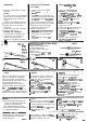
Außenbeheizte Lötspitzen
8
Bits heated from outside
Pannes
3
chauffage
exterieur
Klemmschraube
Clamp
screw
Vis de blocage
..
“1-h_%
@
Iqnenbeheizte
Lötsp!tzen
@
Bits
hea!ed
from
inside
Pannes a chauffage
interieur
Spitzenhaltefeder
Fixing
Clip
for bits
Lötspitze
Klemmschlitz Heizkörper
%;nmg
tip Clamp
slrt
Heating element
Fente
Rbsistance
(iJ Nur ERSA Multi-Pro
0
ERSA Multi-Pro
only
Seulement pour
ERSA Multi-Pro
Federhaken aus Spitzenbohrung heben (1)
und Spitze mit Flachzange abziehen (2).
Unhook spring hook from the hole (1)
and
pull
tip off with flat pliers (2).
Mousqueton hors du trou de
Panne
(1) et tirer
cette
derniere
a
I’aide
d’une
pmce
plate (2).
_
*,