Outer Skin Kit & Flue: IB600, IB850, IB1100 Installation Manual Please see IB series product installation guide for details of installing the gas fire into this preformed metal cavity. Important: The appliance shall be installed in accordance with; • This installation instruction booklet • Local gas fitting regulations • Municipal building codes • Electrical wiring regulations • AS 5601, Gas installations / NZ5261 Gas Installation • Any other relevant statutory regulations.
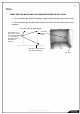
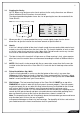
Note: THERE ARE TWO MAIN THINGS TO CONSIDER BEFORE INSTALLATION • You will need to get 230/240 Volt power supply to the back right corner of the cavity • You will need to get gas pipe to one of the three corners of the cavity by removing a knock out Plan view from top looking down. Install gas lines to any of these 3 points. Leave enough piping to reach the front right hand corner of the OSK once installed. Electrical point of entry.
Contents: Section: • Product Description 1.0 • Creating the Cavity 2.0 • Hearth 3.0 • Raised Installations Up a Wall 4.0 • Wall Linings 5.0 • Mantle Clearance 6.0 • Television Clearance 6.1 • Corner Installations 7.0 • Power Supply 8.0 • Installing the Flue System 9.0 • Flue Assembly (NZ ONLY) 10.0 • Flue Assembly (Australia ONLY) 10.2 • Flue Clearance 10.5 • Assembling the Outer Skin Kit 11.0 • Fixing the Outer Skin Kit to the Cavity 12.0 • Laying Gas Pipe 13.
1.0 Product Description: The Escea IB600 Outer Skin Kit (New Zealand only), IB850 Outer Skin Kit and IB1100 Outer Skin Kit are to be used for all installations. They seal the cavity and isolate the fire from air pressure changes within the cavity. The only instance that the OSK might not be fitted is in a New Zealand installation within a full masonry chimney that is not open to any other building space.
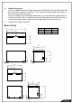
2.0 Creating the Cavity: NOTE: When using designer series fascia options the fire cavity dimensions are different. Check individual fascia instructions for more details. The dimensioned drawing below shows the size of opening that must be created to fit the Outer Skin Kit. Note: It is not necessary to line the cavity. Ideal Cavity Dimensions: All dimensions in millimetres IB Series IB600 IB850 IB1100 A 700 960 1260 B 585 560 560 C 565 565 565 2.
150 6.0 6.1 Mantle Clearance: Please refer to the diagram to the right. Mantles or protruding ledges mounted above the heater that are made from combustible materials, must not extend from the wall outside of the dimensions shown. 6 100 300 200 Television Clearances: The following are the recommended minimum clearances for the location of any electrical equipment (such as Plasma TV, LCD TV or home theatre) above an escea IB Series gas fire.
8.0 Power Supply: The electrical cord (either of the fire, or an extension cord) should pass through the ‘Outer Skin Kit’ as shown, through the supplied ‘Cord Strain Relief Bush’. Locating the power outlet within the cavity makes the installation very neat but the provision MUST be made to be able to switch the power supply off and on (electrical isolation switch) and MUST be accessible after the heater has been installed.
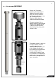
9.0 Installing the Flue System NZ ONLY: Non-Masonry Timber Frame Cavity: The heater must be flued to the outside via a 100mm diameter stainless steel flue that is covered by a 150mm diameter liner. This must be installed in accordance with the requirements of AS5601 / NZ5261. The minimum flue length = 3.6m vertical height It is important to check that you have all the necessary flue parts before beginning your installation.
10.0 Flue Assembly NZ ONLY Secure the Flue spacer bracket to the top section of 100mm Flue and insert the cowl, this can be riveted or held in place with screws (see 10.1 Installing the Flue Terminal). Now slide the 150mm flue onto the bracket. For each section of flue a Spider bracket will be required. These act as spacers for the 150mm flue and should be attached half way along each section of flue. The bottom section is similar to the top assembly.
10.1 Installing the Flue Terminal NZ ONLY Cut the flue termination to the height specified on the attached “Flue position” diagrams and leave a vertical offset of 20 - 30mm between the inner and outer as shown. Slide the flue liner sleeve over the liner and push it down about 150mm out of the way. Fit the flue spacer bracket between the flue and flue liner. Cut & bend an 80mm by 100mm flap and bend towards the inner flue as shown below. Fit cowl and drill trough the flap, flue and cowl stem.
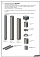
10.2 Flue Kits AUSTRALIA distributor for availability) ONLY: (Glen Dimplex kits only shown. Check with local 552327 Standard Flue Kit 552332 Offset Flue Kit Black 552333 Offset Flue Kit Galvanised 630077_5 Outer Skin Kit Installation Manual.
10.3 Installing the Flue System AUSTRALIA ONLY: Non-Masonry Timber Frame Cavity: The heater must be flued to the outside via a 100mm diameter inner flue that is covered by a 150mm diameter liner. This must be installed in accordance with the requirements of AS5601 and local codes. The minimum flue length = 3.6m vertical height 10.4 AUSTRALIA ONLY Consult the installation instructions that come with your flue kit. To ensure safety the flue kit must be installed according to those instructions.
6. Fix an appropriate weather shielding to the outer liner at the penetration and seal to the roof or chimney using an appropriate sealer. 7. Fit the gas cowl. 8. Once gas fireplace is operational check the installation for flue spill where possible 9. Note: It is the installer’s responsibility to ensure the installation complies with AS5601 2002 and all relevant local codes. 630077_5 Outer Skin Kit Installation Manual.
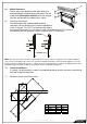
The top of the flue must be capped with an appropriate and approved anti down draft cowl. All the required flue components are available from your escea dealer in both kitset form and as individual components. 500m m cleara nce to neare st part o f roof Seal - Deck Tight or similar Trimmers shown diagrammatic Gap between flue shield and any timber 25 25 Angle fixing bracket supplied with flue kit.
FROM AS5601, please ensure compliance to all other relevant sections of this code. 2.6.13 FLUE TERMINALS 2.6.13.1 Location The termination point of a flue shall be located in relation to any associated building and to neighboring structures so that wind from any direction is not likely to create a downdraught in the flue or chimney. Except where 2.6.13.
10.6 Flue Clearance: 630077_5 Outer Skin Kit Installation Manual.
630077_5 Outer Skin Kit Installation Manual.
10.7 Fixing the Flue to the Cavity A length of angle should be attached to the inside of the timber frame cavity to hold the flue in place. Once you have fixed the angle to the inside of the cavity holes must be drilled to secure it to the flue. Screws or rivets can be inserted directly into the 150mm flue to hold it in place. To make sure the flue is installed at the correct height, a piece of timber can be cut to 600mm and between the fire base level and the bottom of the flue.
11.0 Assembling the Outer Skin Kit: Included in the Outer Skin Kit is: - 1x Top-Rear panel - 1x Top-Front panel - 2x Side panels - 1x Rear panel - 1x Base panel 11.1 Attach the Sides to the Base: Attach Side panels to Base, make sure Base panel flanges are on the outside, and the large flange of the Side panels faces the front. The Right Side has a rectangular cutout, It is important that this is on the right hand Side and that the circular knock-outs are At the base of the Outer Skin Kit as pictured.
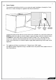
12.0 Fixing the Outer Skin Kit into the Cavity: Slide the Outer Skin Kit into the cavity, and secure it to the wall using screws or other fasteners through the slots at the front of the side panels. The cavity is now ready for the installation of the Gas Fireplace. 630077_5 Outer Skin Kit Installation Manual.
13.0 Laying Gas Pipe: Gas pipe should be sized as per the requirements of AS5601 / NZ5261:2003. The pipe sizing must be sufficient to deliver the following volume of gas to the heater with all other gas appliances in the home running at the same time; IB600 IB850 IB1100 New Zealand 36 MJ/hr 42 MJ/hr 42 MJ/hr Australia ----40 MJ/hr 40 MJ/hr 13.1 This fire has been supplied with a 300mm long flexible inlet connection to make connecting the gas supply easy and safe.
14.0 Gas Fireplace Installation: Attached to the base of the Outer Skin Kit are guide rails. The inside edge of these rails will line up with the outside edge of the two outer under base supports. When the parts are lined up, push the fire towards the back of the Outer Skin Kit until it cannot be pushed back any further. The front of the firebox should now be sitting flush with the OSK. 15.
16.0 Securing the Flue Sleeve NZ ONLY: Tighten the flue sleeve with a screw driver and spanner, ensure a tight and secure seal has been made between the flue assembly and the flue outlet spigot. 16.1 Inserting the OSK Lid: Once the previous steps have been completed you slide the 180mm flue sleeve (NZ ONLY) down until it rests on the lid of the Outer Skin Kit, this will prevent anything touching the inner flue. The final step is to attach the front lid to the OSK.