
Datasheet

www.e-t-a.de
2
Thermal Overcurrent Circuit Breaker 1110-...
1824
1
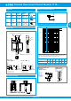
This is a metric design and millimeter dimensions take precedence (
mm
)
inch
All dimensions without tolerances are for reference only. In the interest of improved design,
performance and cost effectiveness the right to make changes in these specifications
without notice is reserved. Product markings may not be exactly as the ordering codes.
Errors and omissions excepted.
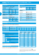
Standard current ratings and typical internal resistance values
Current
rating (A)
Internal
resistance (Ω)
Current
rating (A)
Internal
resistance (Ω)
0.05 442 2.5 0.19
0.1 110 3 0.12
0.2 27.8 3.5 0.09
0.3 12.4 4 0.07
0.4 7.0 5 0.05
0.5 4.5 6 0.04
0.6 3.1 7 ≤ 0.02
0.7 2.3 8 ≤ 0.02
1 1.1 10 ≤ 0.02
1.5 0.41 12 ≤ 0.02
1.8 0.38 15 ≤ 0.02
2 0.25 16 ≤ 0.02
Ordering information
Type No.
1110 snap in panel mounting
Mounting
F1 panel thickness 0.8...1.6 mm (.031 -.063 in)
F2 panel thickness 1.8...3 mm (.071-.118 in)
Number of poles
1 1-pole protected
Actuator style
2 black push button/white indicator ring,
push-push function
Terminal design
P1 blade terminals A6.3-0.8 (QC .250)
Characteristic curve
M1 medium delay
Current ratings
0.05...16A
1110 - F1 1 2 - P1 M1 - 0.05 A = ordering example
Please be informed that we have minimum ordering quantities to be
observed.
Technical data Technical data
Preferred types Short description Preferred ratings (A)
1 2 3 5 6 8 10 16
1110-F112-P1M1- panel thickness 0.8…1.6 mm • • • • • • • •
1110-F212-P1M1- panel thickness 1.8…3 mm • • • • • • • •
Preferred types
Preferred types are E-T-A products most frequently used by E-T-A
customers. We manufacture E-T-A preferred types in particularly high
volumes.
Custom designed versions
Looking for a version you cannot find in our ordering number code?
Please get in touch. We will be pleased to find a solution for you.
For further details please see: www.e-t-a.de/ti_e
Voltage rating AC 250 V; DC 50 V
Current rating 0.05...16 A
I
n
operations U
n
I
0.05...10 A 10000 AC 250 V 1xIn
0.05...10 A 10000 DC 28 V 1xIn
0.05...10 A 6000 DC 50 V 1xIn
12...16 A 2000 DC 50 V 1xIn
Ambient temperature -20...60 °C (-4...+140 °F)
Insulation co-ordination
(IEC 60664)
2.5 kV/2 reinforced insulation in
operating area
Dielectric strength operating area
test voltage AC 3 000 V
Insulation resistance > 100 MΩ (DC 500 V)
Interrupting capacity I
cn
AC 250 V: 0.05...10 A 8 x I
N
DC 50 V: 0.05...6 A 10 x I
N
7...16 A 130 A
DC 28 V: 7...10 A 200 A
Interrupting capacity
I
N
U
N
(UL 1077) 0.05...6 A AC 250V 1 000 A, C, 1
7...16 A AC 125V 1 000 A, U, 1
0.05...16 A DC 50V 1 000 A, C, 1
Degree of protection
(IEC 60529)
operating area
terminal area
IP40
with protective cover IP64
IP00
with protective cover IP64
Vibration 8 g (57-500 Hz) ± 0.61 mm (10-57 Hz),
to IEC 60068-2-6, test Fc,
10 frequency cycles/axis
Shock 30 g (11 ms)
to IEC 60068-2-27, test Ea
Corrosion 96 hours at 5 % salt mist,
to IEC 60068-2-11, test Ka
Humidity 240 hours at 95 % RH
to IEC 60068-2-78, test Cab
Mass approx. 12 g