
Manual

ETC Installation Guide
Echo Network Termination Kit
Echo Network Termination Kit Page 2 of 2 Electronic Theatre Controls, Inc.
Step 5: If the Category 5 cable running to the enclosure does not have a female RJ45 connector,
reference the included Ethernet Cat5 Termination Kit Setup Guide to terminate
Category 5 wiring to the provided Cat5 mounting box and connector.
• When installing, attach the Cat5 mounting box at the back of the enclosure, left of
the neutral lug and at least one inch from any exposed copper.
Install the I/O card
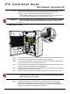
Step 1: Align the network termination card to the mounting studs at the lower left of the enclosure.
Step 2: Use four of the included screws to secure the card to the enclosure.
Step 3: Connect the included Ethernet patch cable from the previously installed Cat5 termination
box to the receptacle on the network termination card.
Step 4: Tie back and secure the Ethernet patch cable neatly inside the enclosure to ensure it does
not interfere with module installation and DRd operation.
Step 5: Replace the dimmer modules, Station Power Module and Architectural Control Processor
into the slots they were previously removed.
Step 6: Slide the module retention bar to the right and tighten the screws to secure it in place.
Step 7: Supply power to the DRd enclosure.
Step 8: Unless structural changes are being made to the existing system, no dimming or
architectural re-configuration should be necessary. If the system is being modified,
reference the related Architectural Control Processor Configuration and Programming
Guide for configuration setup and operation information.
WARNING:
Failure to properly space the mounting box from the exposed power lugs could
result in damage to the DRd and its components and poses a serious safety
risk.
WARNING:
Never power up or operate the Unison DRd enclosure without all modules
installed. Failure to comply exposes you to dangerously high voltages that may
result in death by electrical shock.