
Owner's manual


IES PowerModule Operators’ Manual v1.4 Isine 3
2.3.5 DMX data signals
All PowerModules are controlled by DMX 512
connected by a two-pair and shield high-speed data
cable with XLR 5-pin connectors (male = input;
female = output).
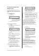
Pin connections are:
1 0V shield
2 DMX -
3 DMX +
4 DimSTAT -
5 DimSTAT +
The DMX network supports up to 32 PowerModules
connected to one line. For larger installations where
more DMX lines are required, the use of a DMX
booster/isolator is recommended. Any
booster/isolator used has to accommodate bi-
directional data on pins 4 and 5 for DimSTAT to
operate. Suitable boosters are IES code 9601 (5
channels) or 9815 (10 channels).
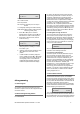
Termination is required for both DMX and DimSTAT
data on all networks. The last DMX output socket in
the line has to be terminated with two 120Ω 1/4 Watt
resistors connected between pins 2 and 3 (DMX)
and between 4 and 5 (DimSTAT). A ‘dummy plug’
XLR male connector with the termination resistors
fitted is recommended for this purpose.
2.4 Safety
Even though the PowerModule is equipped with the
latest electronic safety protection features and in
some cases an RCBO input protection device, all
normal electrical safety procedures must be applied.
Do not use the dimmer if the mains input cable has
been damaged, or the body of the case is not intact.
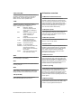
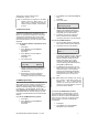
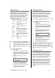
3 Control panel layout
on
dmx
DMX INST CHAS
PWR MA NCONF
INF O CH KEXIT
ENT
L D :001*
CH 1 2 3 4 5 6 A:016*
ON LED
Illuminates red when power is applied, and the
RCBO or MCB is switched on.
DMX LED
Illuminates red continuously when valid DMX is
present. LED flashes when there is no DMX signal.
ENT & cursor arrows
ENT (ENTer) completes a programming step and
records the information in the memory
The four cursor arrows provide navigation through
the set-up menu, and the means to enter data.
Ï Up cursor. Higher level menu feature
or move cursor up in display screen or
number increment.
Ð Down cursor. Lower level menu
feature or move cursor down in display
screen or number decrement
Í Left cursor. Move cursor left in display
screen
Î Right cursor. Move cursor right in
display screen
DMX
Selects DMX address per channel.
INST
INSTall function. To set-up dimmer functionality
options as follows:
•
Line Voltage, frequency and current
•
DimSTAT communication address
•
DMX failure options
•
DMX backup levels
•
DMX configuration (individual or combined)
•
Channel configuration (individual or
combined)
•
Sleep mode
•
Voltage regulation
•
Current limit
•
Minimum level reset (preheat off when DMX is
not present)
• Voltage calibration
• Factory reset
• Channel information
• Password set-up
•
Dimmer hardware configuration