
Owner's manual


IES PowerModule Operators’ Manual v1.4 Isine 6
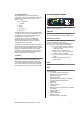
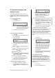
CH ST SP L FADE
01 00 1,0 OFF
where:
CH is chase number
ST is step number
SP is speed (in seconds) from one step to
another
L is a bargraph showing the master intensity
FADE selects either a fading chase (ON) and
a switching chase (OFF)
3. Press Í or Î to put the underline
beneath the CH number, and use Ï and
Ð to select the chase number required.
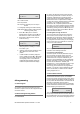
4. Press ENT to start the chase, and the
screen shows e.g.:
CH __ AUTO
05 01 1,0 OFF
5. The step number will increment as the
chase progresses, restarting at 1 at the
end of each cycle.
6. With the chase number underlined, press
Ï or Ð to switch to another chase
pattern.
7. Use Í and Î to underline (select) the
level or FADE and press Ï or Ð to adjust
the master level for each step (shown on
the bargraph) and to choose between
FADE ON (fades between steps) and
FADE OFF (switches between steps).
6 Programming
6.1 Flow diagram
An overview of the flow chart showing the menu
structure and options is shown as an appendix at the
end of this manual.
6.2 General Programming Advice
6.2.1 Passwords
For clarity, the following sections which describe
programming activities do not refer to the entry of
passwords. Passwords are included to prevent
unauthorised access to the DMX, CONFigure and
INSTall menu trees. The passwords are 4-digit
numbers with a factory default of 0000 (no password
necessary). It is possible to have the same
password for all, or separate passwords for each
menu tree. If any of the protected menus is selected,
the subsequent screen requests a password. This is
achieved by pressing the relevant Í and Î cursor
buttons to select the digit, and the Ï and Ð cursor
buttons to enter the number.
6.2.2 Navigation through the menus
The cursor buttons are used to move around the
menu screens, and to activate a set-up option or
parameter prior to adjustment. When a parameter or
option is activated, it is shown in square brackets,
e.g. [240] and it is this item which you are changing
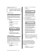
on the screen. When you press ENT to confirm the
change, the screen will show:
DATA IS STORED
IN MEMORY
As this happens for each menu option, it is not
included in each following instruction.
6.2.3 Channel characteristics
All dimmer-specific functional parameters may be
set on a dimmer-per-dimmer basis. Thus each
dimmer may have a different response time, curve,
maximum level etc. if required. Alternatively, all
dimmers in one PowerModule can be programmed
together, depending on whether the dimmer set-up
has been set to ‘SINGLE or ‘JOINED’ (see
paragraph 6.4.1). If the configuration is set to single,
a number is shown in each relevant channel
reference [4], and if all dimmers are programmed
together, a T is shown in square brackets [T]. Note
that if T is activated, an underscore bar is added,
making it appear as an ‘I’.
6.3 Front Panel Controls
All of the performance and control characteristics,
measurements and status reports, are available
from the front panel controls and LCD screen. When
power is applied and the MCB or RCBO is switched
on, the power LED will illuminate. The DMX LED will
illuminate if a valid DMX signal is present.
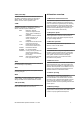
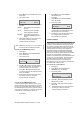
During the power-up reset process, the LCD display
shows identification details and the software version
before displaying the output screen:
L: _ D:001?
CH:123456 A:032v
This display shows the channel levels (bargraphs at
the top left), the DMX address of the first channel in
the PowerModule (D:xxx) and the DimSTAT address
of the unit (A:xxx). The number of bargraphs shown