
Owner Manual


YOUR REMOTE NOW HAS FULL CONTROL OF THE FAN AND LIGHT .
OPERATION DISTANCE 20 FEET
MODEL:
RE-011
TRANSMITTER
Optional Wall Mounting for Transmitter Holder
Place in accessible area of your home, and screw the
transmitter holder into wall using the two screws
provided,slide hand unit into holder.
4.TROUBLE SHOOTING GUIDE1.Fails to operate
a. Power to receiver ?
b.Receiver wired correctly ?
c.Fan manual speed control in highest position ?d.Light kit switch turned on ?
e.Good battery in the transmitter ?
f. Code set at exact same positions in both transmitter and receiver ?
2.Won' t operate at distance
MAX. Motor amps: 1.0
MAX.Light watts: 180-(incandescent, or ballast non-dimmer, or LED)
If transmitter operates fan/light kit when up close,but not at 20 feet away.
Try placing the brown antenna wire higher,up through ceiling/outside the junction box.
NOTICE!
Your ceiling fan and light kit assembly must meet the following requirements:
1.Do not use with solid state fans.
2.Electrical rating: 120v 60Hz 3.5A
WARNING
TO REDUCE THE RISK OF SHOCK, THIS FAN MUST BE INSTALLED WITHAWALL CONTROL/SWITCH.
FCC Statement:
1. This device complies with Part 15 of the FCC Rules.Operation is subject to the following two conditions:
(1) This device may not cause harmful interference.
(2)This device must accept any interference received, including interference that may cause undesired operation.
2.Changes or modifications not expressly approved by the party responsible for compliance could void the user's
authority to operate the equipment.
NOTE:This equipment has been tested and found to comply with the limits for a Class B digital, pursuant to Part 15 or
the FCC Rules.These limits are designed to provide reasonable protection against harmful interference in a residential
installation.This equipment generates, uses and can radiate radio frequency energy and, if not installed and used in
accordance with the instructions, may casue harmful interference to radio communications,
However, there is no guarantee that interference will not occur in a particular installation.If the equipment does cause
harmful interference to radio or television reception, which can be determined by turning the equipment off and on, the
user is encouraged to try to correct the interference by one or more of the following measures:
--- Reorient or relocate the receiving antenna.
--- Increase the separation between the equipment and receiver.
--- Connect the equipment into an outlet on a circuit different from that to which the receiver is connected.
--- Consult the dealer or an experienced radio/ TV technician for help.
If other fans or supply wires are different color, have this unit installed by qualified licensed electrician.
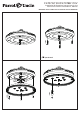
e.Push all connected wires up into junction box.
f. Lay the brown antenna wire on top of the receiver, and put the receiver into the mounting bracket.
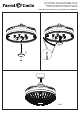
g.Reinstall the canopy on the mounting bracket.
h.Restore power.
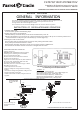
3.OPERATINGTRANSMITTER:
A. lnstall1.5 volt battery(not included).(To prevent damage to transmitter, remove the battery if not used for along time).
B.Store the transmitter away from excessive heat or humidity.
C.This remote control unit is equipped with roll code combinations. In order to prevent possible interference from or to
other remote units such as garage door openers, car alarm or security system. If you find that your fan and light kit go
on and off without using your remote control, simply change the code combination in your transmitter and receiver.
D. Operating the buttons on the panel of the transmitter.
3 key -for fan high speed.
2 key-for fan medium speed.1 key-for fan low speed.
OFF key-for fan off.
LIGHT key-for light on and off.
2hr , 4hr , 8hr button to set the FAN sleep timer
F4707Q110V/F4707BK110V
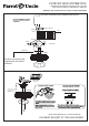
Installation & Operating Instructions for the
Parrotuncle Owner's Installation ,Manual
WARNING: SHUT POWER OFF AT FUSE OR CIRCUIT BREAKER