OWNER & INSTALLATION MANUAL Affinity 30Gp Cooktop Evo Affinity 30Gp Residential Series Manual-Controlled Gas Cooktop With Standing Pilot Light For Indoor Use Only This appliance and its individual shutoff valve must be disconnected from the gas supply piping system during any pressure testing of system at test pressures in excess of 1/2 PSI (3.5kPa). Certification: ANSI Z83.11-2016 / CSA 1.8-2016.
INSTALLATION INSTRUCTIONS Affinity 30Gp Warnings FOR YOUR SAFETY FOR YOUR SAFETY 1. Do not store or use gasoline or other flammable vapors and liquids under this appliance or in the vicinity of this or any other appliance. 2. An LP Tank not connected for use shall not be stored in the vicinity of this or any other appliance. If You Smell Gas: 1. Shut off gas to appliance. 2. Extinguish any open flame. 3. Remove grill cooking surface. 4.
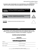
INSTALLATION INSTRUCTIONS Affinity 30Gp THIS MANUAL MUST BE RETAINED FOR FUTURE REFERENCE. READ, UNDERSTAND, AND FOLLOW THE INSTRUCTIONS AND WARNINGS CONTAINED IN THIS MANUAL. WARNING POTENTIALLY HAZARDOUS SITUATION WHICH, IF NOT AVOIDED, COULD RESULT IN DEATH OR SERIOUS INJURY CAUTION POTENTIALLY HAZARDOUS SITUATION WHICH, IF NOT AVOIDED, MAY RESULT IN MINOR OR MODERATE INJURY. CAUTION Helpful tips and technique instructions are shown.
INSTALLATION INSTRUCTIONS Affinity 30Gp READ FIRST IMPORTANT PRODUCT AND SAFETY INFORMATION WARNING INSTALLATION OF THIS UNIT MUST BE DONE BY A QUALIFIED PLUMBER. INCORRECT INSTALLATION CAN CAUSE INJURY TO PERSONNEL AND/ OR DAMAGE TO EQUIPMENT. THIS UNIT MUST CONFORM WITH ALL LOCAL CODES, OR IN THE ABSENCE OF LOCAL CODES, WITH THE NATIONAL FUEL GAS CODE, ANSI Z223.1/NFPA 54, OR THE NATURAL GAS AND PROPANE INSTALLATION CODE, CSA B149.1, AS APPLICABLE INCLUDING: 1.
INSTALLATION INSTRUCTIONS Affinity 30Gp SAFETY LABEL Evo, Inc., 20560 SW 115th Ave., Tualatin, OR 97062 USA Phone 503.626.1802 | Fax 503.213.5869 | www.evoamerica.com | support@evoamerica.
INSTALLATION INSTRUCTIONS Affinity 30Gp EVO RESIDENTIAL LIMITED WARRANTY TERMS Evo, Incorporated warrants to the original residential consumer-purchaser that the Evo grill shall be free from rust-through on all metal surfaces and shall be free from defects in materials and workmanship under normal and reasonable use from the original date of purchase.
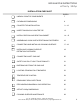
INSTALLATION INSTRUCTIONS Affinity 30Gp INSTALLATION CHECKLIST UNPACK COOKTOP COMPONENTS PAGE # 7 CLEARANCE DIMENSIONS 8 COUNTER TOP INSTALLATION 9 - 12 INSERT CHASSIS IN COUNTER TOP 13 INSTALL DRIP PAN AND DRIP PAN GASKET 14 - 15 ASSEMBLING COOK SURFACE RETAINING FASTENERS 16 CONNECTING AND INSTALLING COOKING SURFACE 17 - 18 INSTALLING COOKING SURFACE 19 RETENTION FASTENERS CONNECTING INLET GAS LINE 20 SAFETY GAS PILOT LIGHT FUNCTIONALITY 21 BLEEDING AIR FROM THE GAS LINE 22 LIGHTING
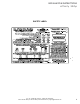
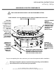
INSTALLATION INSTRUCTIONS Affinity 30Gp UNPACKING COOKTOP COMPONENTS THE COOK SURFACE IS HEAVY. USE CAUTION WHEN LIFTING. COOK SURFACE: LIFT AND SEPARATE COOK SURFACE FROM UNIT AND PLACE NEXT TO INSTALLATION AREA. DRIP PAN: UNLATCH PAN FROM CIRCULAR SKIRT, THEN CAREFULLY LIFT AND SEPARATE DRIP PAN FROM UNIT AND PLACE NEXT TO INSTALLATION AREA. TAKE CARE NOT TO SCRATCH DRIP PAN DURING INSTALLATION. REMOVE TIE DOWN BOLTS AND TABS HOLDING CHASSIS TO PACKING CRATE BASE USING 7/16” WRENCH.
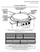
INSTALLATION INSTRUCTIONS Affinity 30Gp CLEARANCE DIMENSIONS 36” CLEARANCE FROM COOKING SURFACE TO COMBUSTIBLE CEILING MATERIALS. 12” CLEARANCE FROM COOKING SURFACE TO COMBUSTIBLE BACK WALL MATERIALS. 12” CLEARANCE FROM COOKING SURFACE TO COMBUSTIBLE SIDEWALL MATERIALS. IF INSTALLING ALONGSIDE ANOTHER 30Gp UNIT, PROVIDE 2” MINIMUM CLEARANCE FROM EDGE OF DRIP PANS. Minimum 3” clearance required under unit venting to 22 sq../in of combustible air.
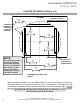
INSTALLATION INSTRUCTIONS Affinity 30Gp COUNTER TOP INSTALLATION (1 of 4) TOP VIEW COUNTER TOP WITH SUBSTRATE UNDERLAYMENT CABINETRY BOX: MINIMUM 1-3/16” (3CM) BELOW COUNTER TOP SURFACE. NOTE: COUNTER TOP OVERHANG TO CABINET FRONT If the dimensions for the counter top overhang and counter top depth cutout are not followed, there will be a conflict with the door swing which allows access to the waste containers.
INSTALLATION INSTRUCTIONS Affinity 30Gp COUNTER TOP INSTALLATION (2 of 4) EXAMPLE: TILED COUNTER TOP WITH SUBSTRATE. FINISHED COUNTER TOP THICKNESS SHOULD BE 1-3/16” (3CM). CABINET FRAMEWORK Metal right angle mounting brackets supplied with unit are 1/16” thick. Mount angle brackets as shown. Unit slides into framework and rests on top of brackets. Brackets are slotted for fasteners at each four corners. SHELVING OR DRAWERS CAN BE INSTALLED UNDER THE UNIT IF DESIRED.
INSTALLATION INSTRUCTIONS Affinity 30Gp COUNTER TOP INSTALLATION (3 of 4) FINISHED CABINET FACE SET BACK FROM FINISHED COUNTER TOP FRONT EDGE METAL RIGHT ANGLE MOUNTING BRACKETS (SUPPLIED) IF DESIRED, SHELVING OR DRAWERS CAN BE INSTALLED UNDER THE UNIT IF DESIRED. SIDE VIEW Example of 3/8” tile with substrate for a minimum 1-3/16” (3cm) overall. Make sure you allow for the counter top overhang as shown. 11 Evo, Inc., 20560 SW 115th Ave., Tualatin, OR 97062 USA Phone 503.626.1802 | Fax 503.213.
INSTALLATION INSTRUCTIONS Affinity 30Gp COUNTER TOP INSTALLATION (4 of 4) BLACK O-RING UNDER DRIP PAN BEAD CORRECT ALIGNMENT OF DRIP PAN AND CHASSIS TO COUNTER TOP INCORRECT ALIGNMENT OF DRIP PAN AND CHASSIS TO COUNTER TOP POSSIBLE REASONS FOR INCORRECT ALIGNMENT: 1. TOP OF CABINETRY BOX IS LESS THAN 1-3/16” (3CM) FROM COUNTER TOP. 2. CHASSIS MOUNTING BRACKETS ARE TOO HIGH.
INSTALLATION INSTRUCTIONS Affinity 30Gp INSERT CHASSIS IN COUNTER TOP USE SUPPLIED 1/4” FASTENERS TO BOLT CHASSIS TO ANGLE BRACKETS. Slide the Affinity 30Gp chassis into the counter top mounting enclosure so it rests on top of the installed brackets. Bolt unit to angle brackets using supplied 1/4” x 20 fasteners. Gas Installation must be done by a licensed plumber in accordance with local guidelines once unit has been completely installed. Refer to pages 1718 and 21 for further instructions. 13 Evo, Inc.
INSTALLATION INSTRUCTIONS Affinity 30Gp POSITIONING DRIP PAN DRIP TRAY CATCH Slide drip tray over chassis circular skirt positioning spillover slots to the corresponding slots of the top chassis deck. Notice the drip pan catches showing through the inside cutout locations of the circular chassis skirt. From the inside of the skirt, use each of the three latches to pull the drip pan down into the counter. Evo, Inc., 20560 SW 115th Ave., Tualatin, OR 97062 USA Phone 503.626.1802 | Fax 503.213.5869 | www.
INSTALLATION INSTRUCTIONS Affinity 30Gp SECURING DRIP PAN AND GASKET USE NO. 3 PHILLIPS SCREWDRIVER TO SECURE DRIP PAN AT THE ACCESS POINTS. DRIP PAN GASKET SEAM AT REAR CROSS SECTION OF CHASSIS ACCESS SLOT A CROSS SECTION OF DRIP PAN TOP B Chassis Skirt Hook drip pan latch under chassis catch and tighten screw at chassis access slot. CROSS SECTION OF DRIP PAN EDGE C Drip Pan Slip gasket ring onto top of drip pan so it creates a seal to the chassis skirt.
INSTALLATION INSTRUCTIONS Affinity 30Gp ASSEMBLING COOK SURFACE RETAINING FASTENERS IT IS RECOMMENDED THE COOKING SURFACE BE PLACED ON A PROTECTED WORK SURFACE WITH THE FLANGE FACING UPWARD. USING A 7/16” WRENCH, TIGHTEN THE REAR RETAINING BULLET TO THE COOKING SURFACE TAB WITH TWO EACH 1/4” X 20 HEX BOLT AND LOCKING NUT. ENSURE THE BOLTS ARE TIGHTENED SECURELY. LOOP THE J-HOOK THROUGH THE INSIDE SLOT OF TWO TABS AS SHOWN. PLACE REAR RETAINING BULLET FASTENER ON RIGHT HAND SIDE OF TAB.
INSTALLATION INSTRUCTIONS Affinity 30Gp CONNECTING COOK SURFACE PLACE COOK SURFACE ON AN ANGLE WITH BULLET FASTENER FACING DOWN AND REARWARD, ENGAGE BULLET FASTENER TO KEYWAY SLOT ON CHASSIS BACK WALL AND LOWER J-HOOKS INTO FRONT THREADED TUBES. Place cook surface on an angle with Bullet Fastener facing down and rearward. Engage bullet fastener to keyway slot on chassis back wall and lower J-Hooks into front threaded tubes. 17 Evo, Inc., 20560 SW 115th Ave., Tualatin, OR 97062 USA Phone 503.626.
INSTALLATION INSTRUCTIONS Affinity 30Gp INSTALLING COOK SURFACE COOK SURFACE SUPPORT TAB BOTTOM-UP VIEW OF REAR COOK SURFACE CUT AWAY VIEW OF REAR COOK SURFACE SHOWING BULLET ENGAGED IN CHASSIS SLOT A REAR BULLET C B Place cook surface over circular skirt with the three support tabs (located under cook surface) resting on top the chassis skirt. Position the rear support tab of the cook surface to the right of the rear seam of the chassis skirt (A).
INSTALLATION INSTRUCTIONS Affinity 30Gp INSTALLING COOKING SURFACE RETAINING FASTENERS OPEN WASTE DOORS TO LOCATE END OF J-HOOK. TIGHTEN 1/4” X 20 NUT AT END OF EACH J-HOOK. Open both waste doors and at the rear inside corner of the enclosure, tighten 1/4” X 20 nut on end of J-Hook to retain cooking surface for burner chassis. 19 Evo, Inc., 20560 SW 115th Ave., Tualatin, OR 97062 USA Phone 503.626.1802 | Fax 503.213.5869 | www.evoamerica.com | support@evoamerica.
INSTALLATION INSTRUCTIONS Affinity 30Gp CONNECTING INLET GAS LINE FOR YOUR PROTECTION, A QUALIFIED PLUMBER MUST INSTALL THIS COOKTOP. THIS PERSON MUST BE FAMILIAR WITH GAS INSTALLATIONS AND ALL LOCAL CODES. PROPER CONNECTIONS ARE ESSENTIAL FOR SAFE AND EFFICIENT OPERATION. GAS PRESSURES MUST BE CONFIGURED FOR THE TYPE OF GAS USED EITHER NATURAL GAS OF LP PROPANE GAS.
INSTALLATION INSTRUCTIONS Affinity 30Gp SAFETY GAS PILOT LIGHT FUNCTIONALITY ONCE THE CHASSIS IS INSTALLED AND BEFORE CONNECTING TO AN INLET GAS SUPPLY, IT’S RECOMMENDED TO BLEED THE INPUT GAS LINE OF AIR TO REDUCE THE TIME TO ENGAGE THE SAFETY GAS PILOT LIGHT BURNERS.
INSTALLATION INSTRUCTIONS Affinity 30Gp BLEEDING AIR FROM GAS LINE IT IS IMPORTANT TO BLEED OUT THE GAS LINE, OR ‘PURGE’, TO ENSURE ALL AIR POCKETS ARE REMOVED.
INSTALLATION INSTRUCTIONS Affinity 30Gp LIGHTING STANDING PILOT BURNERS INNER BURNER CONTROL KNOB OUTER BURNER CONTROL KNOB IGNITION BUTTON INNER Pilot Light Button OUTER Pilot Light Button TRIANGULAR FLAME VIEWING PORTALS To Light The Inner and Outer Standing Pilot Burners: STEP 1: The external gas shut-off valve must be in the ON position. STEP 2: Press the Ignition Button and simultaneously press the Inner Burner Pilot Light Button.
OPERATOR INSTRUCTIONS Affinity 30Gp TEMPERATURE CONTROL OUTER MAIN BURNER CONTROL KNOB INNER MAIN BURNER CONTROL KNOB How To Adjust Inner and Outer Temperature Control Knobs: With both the inner and outer pilot light burners lit and continuously burning, select the inner or outer or both control knobs and choose a temperature setting between Hi, Med and Low.
OPERATOR INSTRUCTIONS Affinity 30Gp REMOVABLE SPILLOVER TRAYS Spillover Slot Removable Waste Pan Access Door Insert waste pan fully into the back of the left and right compartments. Do not operate cook top or clean drip pan into spillover slots without waste pans installed in spillover doors. Failure to install waste pan will result in cooking grease contamination to the underside of door. This requires immediate cleaning.
OPERATOR INSTRUCTIONS Affinity 30Gp RECOGNIZING ABNORMAL GAS OPERATION Right Flame Wrong Flame Yellow Tip Light Blue Dark Blue Excessive Yellow Tipping Light Blue Dark Blue Any of the following are considered to be abnormal operation and may require servicing: • • • • • Excessive yellow tipping of the burner flame (See diagram above). Sooting up of cooking utensils. Burners not igniting properly. Burners failing to remain alight. Gas valves, which are difficult to turn.
OPERATOR INSTRUCTIONS Affinity 30Gp AFFINITY 30Gp DIMENSIONS 30” 762mm Diameter 36 5/32” 914mm 11-7/32” 292mm 27 Evo, Inc., 20560 SW 115th Ave., Tualatin, OR 97062 USA Phone 503.626.1802 | Fax 503.213.5869 | www.evoamerica.com | support@evoamerica.
OPERATOR INSTRUCTIONS Affinity 30Gp COOK SURFACE MAINTENANCE Regular cleaning and care for your Evo Affinity 30Gp cooktop will keep it looking and functioning its best. The cook surface is designed to hold a fine layer of cooking oil creating a ‘seasoning’ on its surface. This seasoning promotes a non-stick cooking surface and is easily maintained. Caring for Evo’s cook surface is much like maintaining cast iron cookware. When the surface requires cleaning, there are a few basic cleaning techniques to use.