
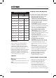
Warranty


5
www.evolutionpowertools.com
EN
Fig. 1
Fig. 2
Fig. 3
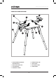
PREPARING THE STAND
WARNING: This stand is quite heavy. If necessary enlist
competent help when lifting, moving or adjusting
the stand.
Take care when deploying the legs and elevating the stand.
Ensure that your hands or ngers cannot become trapped
in any of the mechanisms contained within the stand,
and that no article of clothing, jewellery etc can become
entangled in any part of the stand.
Note: Placing the stand on end or upside down on a clean
work bench (or similar rigid work surface) may help with
the following procedures.
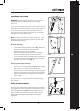
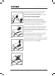
Deploying the legs
• Squeeze the locking/unlocking lever (Fig. 1) towards
the leg to release from the stored position.
• Rotate the leg to its service position.
• Repeat until all four (4) legs have been deployed.
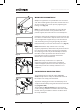
• Ensure that all four (4) legs are locked into their
service position. The hinge latching pins must be fully
engaged with the machined slots incorporated into
the tables corner brackets. (Fig. 2).
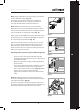
Adjusting the length of the legs
• Push in the inner leg locking pin (Fig. 3) and carefully
slide out the inner leg to the desired position.
• Ensure that the inner leg locking pin is fully engaged
into the relevant hole machined in the outer leg tube.
• Adjust all four (4) legs ensuring that all are set to the
same length.
Place the stand on its legs and test the stand for rigidity
and stability.
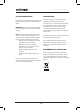
FIXED CLAMP ASSEMBLY
Align the xed clamp’s body and baseplate parts with the
rectangular hole in the metal table and push t the clamp’s
baseplate from below. (Fig.4) Ensure the Nyloc nuts are
inserted into the baseplate so the bolts can be inserted
through the mounting holes from above and gently
tightened.
Fig. 4