
Warranty


7
www.evolutionpowertools.com
EN
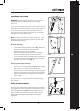
Fig. 9
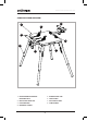
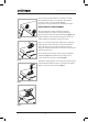
EXTENSION ARMS
(Fig.10)
Note: The supplied extension arms are not ‘handed’ and
will t either the RH (right hand) or LH (left hand) sides of
the machine table.
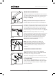
To t the extension arms
• The extension arms slide through the square section
guide tubes located on the underside of the stands
table top (Fig. 11a).
• A locking screw (Fig. 11b) is located on both of the
square section guide tubes.
When an extension arm is adjusted to the required
position, tightening the locking screw will secure the
extension arm in place.
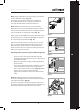
WARNING: The extension arms must not be withdrawn
beyond the maximum safe working limit. To aid the
operator a safety index mark is printed onto the surface of
the extension arms (Fig. 12).
Fig. 11
Fig. 12
(a)
(b)
Fig. 10