
Warranty


8
www.evolutionpowertools.com
Fig. 15
Fig. 16
Fig. 13
Fig. 14
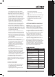
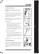
WORKPIECE SUPPORT BARS
Workpiece support bars are provided for each extension
arm. These t through the square tube located at the end
of each arm and are secured in place by tightening the
locking screw (Fig. 13)
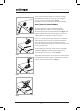
Note: The support bar(s) should be set so that the top
bearing surface matches exactly (and therefore will
provide support) the underside of a secured workpiece.
Usually the underside of a workpiece will be resting on the
base of the vice tted to the chopsaw. If this is the case the
correct height of the support bar(s) can be determined
and checked by placing a long straight edge (or similar
tool) horizontally in and across the machine vice. (Fig. 14)
Note: On Evolution chop saws the rear vice clamp
(angularly adjustable) is fastened directly to the machine’s
base. The front clamp slides across the base to provide
the clamping pressure. Any inserted workpiece should
therefore rest directly onto the base of the machine.
Non-Evolution machines may dier. Consult the
Manufacturers Instruction Manual.
Note: Some chop saw machines are capable of
performing angled cuts. If this facility is employed
additional support (sawhorses or trestles etc) may be
required to provide extra stability and balance to a
workpiece.
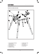
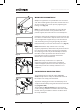
THE UNIVERSAL MOUNTING TABLE
The mounting table has four (4) clamps. (Fig. 15a
& 15b) Two (2) of these clamps are xed to the table. All
the clamps have clamp protectors tted.
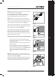
To provide clamping pressure the left hand (LH) pair of
clamps slide individually along slots machined in the table
top. (Fig.16a & 16b)
The handwheels (Fig.16c & 16d) rotate the operating
screws. Turning a handwheel clockwise drives the clamp
inwards. Turning a handwheel counter clockwise drives
the clamp outwards.
(a)
(b)
(a)
(b)
(c)
(d)