
Installation Guide

INSTALLATION PROCESS
X1
X3
X3
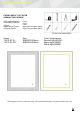
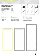
110VAC
Anti-fog
pad
OutputInput
Power Source:
Constant 110AC
power
Output
Dimmer Switch
12V LED Light
110VAC -12VDC
LED
driver
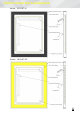
110VAC
Anti-fog
pad
OutputInput
Power Source:
Ceiling/Vanity
Light controlled by
a non-dimmable
switch on the
wall.
Output
Dimmer Switch
12V LED Light
110VAC -12VDC
LED
driver
110VAC
Anti-fog
pad
OutputInput
Power Source:
Ceiling/Vanity
Light controlled
by a non-
dimmable
swithc On/
the wall.
Output
Bypass built-in
touch dimmer switch
12V LED Light
110VAC -12VDC
LED
driver
110VAC
Anti-fog
pad
OutputInput
Power Source:
Ceiling/Vanity
Light controlled
by a dimmable
swithc On/
the wall.
Output
Dimmer Switch
12V LED Light
110VAC -12VDC
LED
driver
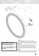
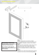
Step 1:
Use an I-Beam level to mount the included
mounting bracket with 3 screws (Use anchor when
it's installed on drywall, concrete or tile surface).
Step 2:
Make sure the circuit breaker for the power source
of the mirror is off. Then connect the neutral
(White), hot (black) and ground (copper wire or
Green) wire between the mirror and the junction
box.
Step 3:
Hang the mirror with desired placement by placing
the mirror's cut out on to the mounting bracket.
E486300
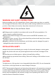
Warning:Always switch off the
electrical supply at the mains during
installation and maintenance.
Do not switch on the electrical supply
at the mains until installation
completed.