
Manual

!
!
!
Installation procedure
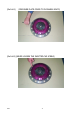
1. Loosen the clutch cover to flywheel bolt and disassemble the kit.
(See attached photo #A1)
Caution
Do not loosen the bolt which fastens the intermediate plate
To the adapter ring. If this bolt is loosened by accident,
tighten once again using Locktight No272 to
13.3 - 19.8 Lb-ft (17.7 - 26.5 Nm). (See attached photo #A2)
2. Use the specified bolt (Flywheel installation bolt)
and fix the flywheel to the crankshaft according to the maintenance manual
issued by the vehicle manufacturer.
Tighten the crank bolt diagonally with equal force applying torque as
specified by the vehicle manufacturer.
Product Number Vehicle Specified torque
GT04SD CORVETTE 74 Lb-ft (99 Nm)
3. Assembly
<Order of assembly> Twin plate
Flywheel -> Flywheel Disc -> Intermediate Plate / Pressure Plate Side Disc /
Clutch cover Assy.
Order of assembly
The clutch cover, intermediate plate set and flywheel should be assembled
in a manner which allows the painted balance mark to be aligned.
Caution
If the marking is not met, it will cause unbalance, noise and
vibration problems.
Caution
Be careful of the direction/location of the discs.
Discs should be facing the same direction.
M190 -4-