RECUMBENT BIKE IMPORTANT: Read all instructions carefully before using this product. Retain this owner’s manual for future reference. The specifications of this product may vary from this photo, subject to change without notice. 1111.
PLEASE DO NOT RETURN THIS PRODUCT TO THE STORE. STOP. Contact customer service if you have any questions regarding assembly or proper operation of the machine. Email us at: Service@paradigmhw.
TABLE OF CONTENTS SERVICE------------------------------------------------------------------------ 2 LABLE PLACEMENT--------------------------------------------------------- 3 PRODUCT SAFETY---------------------------------------------------------- 4 OVERVIEW DRAWING------------------------------------------------------ 5 PARTS LIST--------------------------------------------------------------------- 6 ASSEBMLY GROUP---------------------------------------------------------- 8 GROUP LIST-------------
SERVICE IMPORTANT: FOR NORTH AMERICA ONLY For damaged or defective product, questions, replacement parts or any other service support, please contact our customer service department (8:00 AM - 5:00 PM Pacific Standard Time, Daily) by the below methods: For Best Service, please Email: Service@paradigmhw.com Response Time: 1-2 Business Days Website: www.paradigmhw.com Toll-Free: 1-844-641-7921
Response time may vary.
LABEL PLACEMENT 3
PRODUCT SAFETY Basic precautions should always be followed, including the following safety instructions when using this equipment. Read all instructions before using this equipment. 1. Read all the instructions in this manual and do warm up exercises before using this equipment. 2. Before exercise, in order to avoid injuring your muscles, warm-up exercise for every muscle group is highly recommended. 3. Please make sure all components are not damaged and in working order before use.
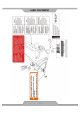
OVERVIEW DRAWING 5
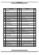
PARTS LIST No. Description Qty No. Description Qty 001 Back and Seat Support Bracket 53x23x2.0 1 028 Bolt M8x18 1 002 Front Stabilizer Ø60x1.5x580 1 029 Locknut M6 2 003 Rear Main Frame 1 030 Bolt M8x70 4 004 Rear Stabilizer Ø60x1.5x580 1 031 Spring 1 005 Front Main Frame 80x40x2 1 032 Cap Nut M8 6 006 Front Handlebar Post Ø50x1.5 1 033 Left Cover 1 007 Seat Cushion 1 034 Right Cover 1 008 Back Cushion 1 035 Screw ST4.
PARTS LIST No. Description Qty No.
ASSEMBLY GROUP 8
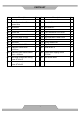
GROUP LIST Assembly Group A1 A2 No. Handlebar Ø25x1.5 1 10 Handlebar Foam Grip Ø30xØ24x510 2 11 Hand Pulse Sensor 2 12 Round End Cap for Handlebar Ø25x1.5 2 26 Screw ST4.2x20 2 6 Front Handlebar Post Ø50x1.5 1 12 Round End Cap for Handlebar Ø25x1.5 2 19 Front Handlebar Foam Grip Ø30xØ24x160 2 63 Extension Wire L=350mm 2 A6 Extension Sensor Wire L=350mm 1 1 Back and Seat Support Bracket 53x23x2.0 1 22 Backrest and Seat Support Bracket End Cap 23x53x1.
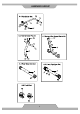
HARDWARE & TOOLS PACK 10
ASSEMBLY Tool: 6mm Allen Wrench 1. Rear Main Frame Installation Remove two Bolts (49), four Bolts (23), and six Washers (24) from the Rear Main Frame (3). Remove bolts with the Allen Wrench provided. Connect the Middle Section Hand Pulse Sensor Wires (55) from the Rear Main Frame (3) to the Extension Hand Pulse Sensor Wires (65) from the Front Main Frame (5). Attach the Rear Main Frame (3) into the Front Main Frame (5) with two Bolts (49), four Bolts (23), and six Washers (24) that were removed.
ASSEMBLY Tool: Multi Hex Tool with Phillips Screwdriver 2. Front and Rear Stabilizers Installation Position the Front Stabilizer (2) in front of the Front Main Frame (5) and align bolt holes. Attach the Front Stabilizer (2) onto the front curve of the Front Main Frame (5) with two Bolts (30), two Curve Washers (25), and two Cap Nuts (32). Tighten cap nuts with the Multi Hex Tool with Phillips Screwdriver provided. Position the Rear Stabilizer (4) behind the Rear Main Frame (3) and align bolt holes.
ASSEMBLY Tool: 6mm Allen Wrench Multi Hex Tool with Phillips Screwdriver 3. Front Handlebar Post and Foot Pedal Installation Remove four Bolts (23) and four Curve Washers (25) from the Front Main Frame (5). Slide the Front Handlebar Post Cover (74) up to the Front Handlebar Post (6).Insert the Tension Cable (40) through into the bottom hole of Front Handlebar Post (6) and pull it out from the square hole of Front Handlebar Post (6).
ASSEMBLY Tool: Multi Hex Tool with Phillips Screwdriver 4. Right and Left Crank Installation The Cranks, Foot Pedals, Pedal Shafts and Pedal Straps are marked “R” for Right and “L” for Left. Insert the pedal shaft of Left Foot Pedal (60) into threaded hole in the left Crank (46). Turn the pedal shaft by hand in the counter-clockwise direction until snug. Note: DO NOT turn the pedal shaft in the clockwise direction, doing so will strip the threads.
ASSEMBLY Tool: 6mm Allen Wrench Multi Hex Tool with Phillips Screwdriver 5. Seat Sliding Tube, Back/Seat Support Bracket, and Handlebar Installation Remove eight Bolts (23) and eight Washers (24) from the Back/Seat Support Bracket (1) and Seat Sliding Tube (15). Remove bolts with the Allen Wrench provided. Insert the Seat Sliding Tube (15) into the Bushings (54) of the Rear Main Frame (3).
ASSEMBLY . Tool: Multi Hex Tool with Phillips Screwdriver 6. Computer Installation Remove four Bolts (39) from the Computer (9). Remove bolts with the Multi Hex Tool with Phillips Screwdriver provided. Connect the Extension Wires (63) and Extension Sensor Wire (64) to the wires that come from the Computer (9). Tuck wires into the Front Handlebar Post (6). Attach the Computer (9) onto the top end of the Front Handlebar Post (6) with four Bolts (39) that were removed.
ASSEMBLY Tool: Multi Hex Tool with Phillips Screwdriver 7. Seat and Back Cushions Installation Remove eight Bolts (21) and eight Washers (58) from the back of the Seat and Back Cushions (7, 8). Remove bolts with the Multi Hex Tool with Phillips Screwdriver provided. Then attach the Seat and Back Cushions (7, 8) onto the Back and Seat Support Bracket (1) with eight Bolts (21) and eight Washers (58) that were removed. Tighten bolts with the Multi Hex Tool with Phillips Screwdriver provided.
COMPUTER OPERATING THE COMPUTER SPECIFICATIONS: TIME --------------------------------------------------- 0:00-99:59 MIN: SEC SPEED ------------------------------------------------ 0.0-999.9 MPH DIST (DISTANCE) ---------------------------------- 0.0-999.9 MILE CAL (CALORIES) ----------------------------------- 0.0-999.9 KCAL ODO (ODOMETER) -------------------------------- 0.0-999.
COMPUTER SPEED: Press MODE button until the screen displays SPEED; the computer will display the current training speed. DIST (DISTANCE): Press MODE button until the screen displays DIST; the computer will display the accumulative distance traveled during workout. When you start to exercise, distance starts counting up from 0.0 to 999.9 miles per 0.1 mile increment. You may also preset target distance before training.
COMPUTER HOW TO INSTALL THE BATTERIES: 1. 2. 3. 4. 5. Remove the battery cover at the rear of computer. Place two "SIZE-AA" batteries into the battery housing. Insure batteries are correctly positioned and battery springs are in proper contact with batteries. Re-install the battery cover. If the display is illegible or only partial legible, remove batteries and wait 15 seconds before reinstalling.
ADJUSTMENTS Adjusting the Tension Control Knob To increase the load, turn the tension control knob in a clockwise direction. To decrease the load, turn the tension control knob in a counterclockwise direction.
TROUBLE SHOOTING & MAINTENANCE Cleaning The recumbent bike can be cleaned with a soft cloth and mild detergent. Do not use abrasives or solvents on plastic parts. Please wipe your perspiration off the recumbent bike after each use. Be careful not get excessive moisture on the computer display panel as this might cause an electrical hazard or electronics to fail. Please keep the recumbent bike, specially, the computer console, out of direct sunlight to prevent screen damage.
WARRANTY MANUFACTURER’S LIMITED WARRANTY Paradigm Health & Wellness warrants to the original purchaser that this product is free from defects in material and workmanship when used for the purpose intended, under the conditions that it has been installed and operated in accordance with Paradigm’s Owner’s Manual.
PARTS REQUEST FORM Paradigm Health & Wellness, Inc. EMAIL THIS FORM WITH YOUR RECEIPT OF PURCHASE TO Service@paradigmhw.