COMMERCIAL 21 For Serial Nos. 850,000 & Higher Part No. 4500-674 Rev.
WARNING CALIFORNIA Proposition 65 Warning The engine exhaust from this product contains chemicals known to the State of California to cause cancer, birth defects, or other reproductive harm. Important: The engine in this product is not equipped with a spark arrester muffler. It is a violation of California Public Resource Code (CPRC) Section 4442 to use or operate this engine on any forest-covered, brush-covered, or grass-covered land as defined in CPRC 4126.
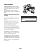
Introduction CONGRATULATIONS on the purchase of your Exmark Mower. This product has been carefully designed and manufactured to give you a maximum amount of dependability and years of trouble-free operation. This manual contains operating, maintenance, adjustment, and safety instructions for your Exmark mower. BEFORE OPERATING YOUR MOWER, CAREFULLY READ THIS MANUAL IN ITS ENTIRETY. Figure 1 1.
Contents Cleaning Under the Belt Cover (Self-Propelled Units Only)........................ 33 Cleaning the Blade Brake Clutch Shield (Blade Brake Clutch Units Only) ................ 33 Cleaning Under the Cover Plate (Non-Blade Brake Clutch Units Only)......................................................... 33 Waste Disposal .............................................. 34 Storage ................................................................. 35 Preparing the Fuel System..............................
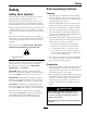
Safety Safety Safe Operating Practices Safety Alert Symbol Training • Read the Operator’s Manual and other training material. If the operator(s) or mechanic(s) can not read English it is the owner’s responsibility to explain this material to them. • Become familiar with the safe operation of the equipment, operator controls, and safety signs. • All operators and mechanics should be trained. The owner is responsible for training the users.
Safety • Inspect the area where the equipment is to be used and remove all rocks, toys, sticks, wires, bones, and other foreign objects which can be thrown by the machine and may cause personal injury to the operator or bystanders. DANGER In certain conditions during fueling, static electricity can be released causing a spark which can ignite gasoline vapors. A fire or explosion from gasoline can burn you and others and cause property damage.
Safety Operation • Never attempt to make wheel height adjustments while the engine is running. WARNING • Stop engine, wait for all moving parts to stop, remove the spark plug wire(s). Operating engine parts, especially the muffler, become extremely hot. Severe burns can occur on contact and debris, such as leaves, grass, brush, etc. can catch fire. – Before checking, cleaning or working on the mower.
Safety Maintenance and Storage • Do Not operate the mower under the influence of alcohol or drugs. • Stop the engine and remove the spark plug wire(s). Wait for all movement to stop before adjusting, cleaning or repairing. • Use extreme care when loading or unloading the machine into a trailer or truck. • Use care when approaching blind corners, shrubs, trees, or other objects that may obscure vision.
Safety Safety and Instructional Decals • Keep all safety signs legible. Remove all grease, dirt and debris from safety signs and instructional labels. • Replace all worn, damaged, or missing safety signs. • When replacement components are installed, be sure that current safety signs are affixed to the replaced components. • If an attachment or accessory has been installed, make sure current safety signs are visible.
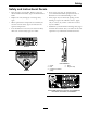
Safety 109-8194 EC21KABBCY, EC21KABBCCA 1. Fast 2. Continuous variable setting 3. Slow 4.
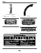
Safety 116-2737 11
Specifications Specifications Model Numbers Serial Nos: 850,000 and Higher EC21ASHN; EC21ASKA; EC21ASKAP; EC21HNBBC; EC21HNBBCX; EC21KA; EC21KACA; EC21KAX; EC21KAY; EC21KABBC; EC21KABBCCA; EC21KABBCX; EC21KABBCY Systems Cutting Deck • Cutting Width: 21 inches (53.3 cm) • Blade Brake: When the blade engagement control is moved to the disengaged position a friction brake pad stops the rotation of the blades. • Blade Size: (1 ea.): 20.88 inches (53.0 cm) • Deck: 21 inches rigid.
Operation Product Overview Operation Note: Determine the left and right sides of the machine from the normal operating position. Controls Blade Control Bail Located on the upper handle as shown in Figure 4. When the blade control bail is depressed, the system senses that the operator is in the normal operator’s position. • For Units with a Blade Brake Clutch: When the blade control bail is released, the system senses that the operator has moved from the normal operating position and will stop the blade.
Operation Throttle-Choke Lever (EC21KABBCX, EC21KABBCY, EC21KABBCCA) Located on the left side of the engine as shown in Figure 11. The lever is used to control engine speed. Moving the throttle to the full forward (Choke) position will place the lever in the choke position. The choke aids in starting a cold engine. Moving the throttle control forward will increase engine speed and moving it to the rear will decrease engine speed. The throttle-choke control also includes an engine kill position.
Operation Pre-Start Fill fuel tank. For best results use only clean, fresh regular grade unleaded gasoline with an octane rating of 87 or higher. To ensure freshness, purchase only the quantity of gasoline that you expect to use in 30 days. Using unleaded gasoline results in fewer combustion deposits and longer engine life. See Engine Owner’s Manual.
Operation 3. For EC21KABBCX Unit: Move the choke control to the Choke position For EC21KABBC Unit: Turn the engine stop switch to “|” (see Figure 5). For EC21KABBC, EC21KABBCCA, EC21KABBCY, EC21KAX, EC21KACA, and EC21KAY Units: Press the primer bulb two times (see Figure 12). Figure 10 Honda unit 1. 2. 3. 4. 5. 6. 7. 8.
Operation Operating the Blade Control Bail (Units Without Blade Brake Clutch) EC21KABBCCA, EC21KABBCX, and EC21KABBCY: Move the throttle to the (Stop) position to kill the engine. 1. Squeeze the blade control bail against the handle. EC21KABBC, EC21HNBBCX, and EC21HNBBC: Press the switch to “STOP” to kill the engine (see Figure 5). 2. Start the engine. 3. When the blade control bail is squeezed against the handle, the blade should engage.
Operation Figure 15 1. Crumpled newspaper 2. 5 inches (12.7 cm) Figure 14 1. Mulch plug 2. Discharge door 3. Lip 4. Mower housing 5. Place the ball of newspaper 5 inches (12.7 cm) in front of the lawn mower. 6. Start the engine. 4. Lower the discharge door. 7. Push the blade control lock lever forward to release the blade control bail (Figure 4). • Removing the Mulch Plug: Note: When grass is thick and lush, clippings may collect on and around the discharge tunnel plug.
Operation DANGER WARNING If the blade brake clutch system is inoperative, the blade will continue to rotate when you release the blade control bail. Contact with the blade could occur, causing serious injury. Adjusting the cutting height levers could bring your hands into contact with a moving blade. A moving blade can cause serious injury. • Stop the engine and wait for all movement to stop before adjusting the cutting height. • Check the BBC operation before each use.
Operation • Mowing with the Grass Bag WARNING A worn grass bag could allow small stones and other similar debris to be thrown in the operator’s or bystander’s direction. Thrown objects can result in serious personal injury or death to the operator or bystanders. Figure 17 1. Front wheel shaft assembly 2. Pull up 3. Height adjuster Check the grass bag frequently. If it is damaged, install a new Exmark replacement bag. 4. Front quadrant block cut heights 5. Pull outward 6.
Operation Operating Tips • For light leaf coverage, set all the wheels at the same cutting height setting. • Review the Safety section and read this manual carefully before operating the lawn mower. • Set the engine speed to the fastest position for the best cutting results. • Maintain a sharp blade throughout the cutting season. Periodically file down nicks on the blade. Replace the blade when necessary with an original Exmark replacement blade. • Clean the air filter frequently.
Maintenance Maintenance Note: Determine the left and right sides of the machine from the normal operating position. WARNING WARNING If you leave the wire on the spark plug, someone could accidentally start the engine. Accidental starting of the engine could seriously injure you or other bystanders. Tipping the lawn mower may cause the fuel to leak from the carburetor or the fuel tank.
Maintenance Maintenance Service Interval Maintenance Procedure Every 100 hours • Change the oil filter (EC21KA, EC21KABBC, EC21KAX, EC21KAY, EC21KABBCX, EC21KABBCY, EC21KACA, and EC21KABBCCA Units). • Check the spark plugs. • Clean the fuel filter element. Every 250 hours • Replace the air filter elements (EC21ASHN Units). (May need more often if they are damaged or excessively dirty.) • Replace the air filter elements (EC21HNBBC and EC21HNBBCX Units).
Maintenance Refer to Checking the Blade Brake Clutch in the Operating Instructions section. DANGER A worn or damaged blade can break. A piece of the blade could be thrown into the operator’s or bystander’s area, resulting in serious personal injury or death. Check the Mower Blade Service Interval: Before each use or daily Always mow with a sharp blade. A sharp blade cuts cleanly and without tearing or shredding the grass blade. 1. Stop the engine and wait for all moving parts to stop. 2.
Maintenance Figure 23 1. Inner cutting edge radius 2. Cutting angle C. Check the balance of the blade by placing the center hole of the blade over a nail or screwdriver shank clamped horizontally in a vise (Figure 24). If either end of the blade rotates downward, file that end (not the cutting edge). The blade is properly balanced when neither end drops. Figure 25 1. Blade Brake Clutch Units 2. Units without a Blade Brake Clutch 6. Return the lawn mower to its upright position. 7.
Maintenance Service Air Filter (Kawasaki Units) Service Interval: Every 25 hours—Clean the foam pre-cleaner (Kawasaki Units). Every 300 hours— Replace the paper air filter (Kawasaki Units). (May need more often in dusty conditions. See the Engine manual for additional information.) Note: Do Not operate the engine without the air filter assembly; extreme engine damage will occur. 1. Stop engine, wait for all moving parts to stop. 2. Disconnect the wire from the spark plug (Figure 11).
Maintenance damaged or excessively dirty.) 10. Install the foam element. 11. Remove dirt from the air cleaner housing and cover using a moist rag. Do Not wipe dirt into the air duct. Note: Do Not operate the engine without the air cleaner assembly; extreme engine damage will occur. 12. Install the filter. 1. Stop the engine and wait for all moving parts to stop. 13. Close the cover. 2. Disconnect the wire from the spark plug (Figure 10). Service Air Filter (EC21HNBBC and EC21HNBBCX Units) 3.
Maintenance Note: Be careful to prevent dirt and debris from entering the air duct leading to the carburetor. 13. Install the air cleaner elements and ensure that they are properly positioned. 14. Securely install the cover with the two wing nuts. Change Engine Oil Service Interval: After the first 5 hours Every 50 hours (May need more often under severe conditions.) 1. Run the engine to warm the engine oil. Note: Warm oil flows better and carries more contaminates. Figure 29 1. Wing nuts 2. Cover 3.
Maintenance Change Oil Filter (EC21KA, EC21KABBC, EC21KAX, EC21KAY, EC21KABBCX, EC21KABBCY, EC21KACA, and EC21KABBCCA) Check Condition Of Belt (Self-Propelled Units Only) Service Interval: Every 40 hours 1. Stop engine, wait for all moving parts to stop. 2. Remove the belt cover to the lawn mower housing. 3. Check the belt for cracks, frayed edges, burn marks or any other damage. 4. Replace the damaged belt. Service Interval: Every 100 hours 1. Run the engine to warm the oil. Check Spark Plugs 2.
Maintenance The fuel filter (screen) element is located inside the fuel tank (if applicable). Adjustments Note: The EC21ASHN does not have a removable fuel tank. Note: Wait for all moving parts to stop and remove spark plug wire before servicing, cleaning, or making any adjustments to the unit. 1. Stop the engine and wait for it to cool down. Adjusting the Self-Propel Drive (Self-Propelled Units Only) Note: Drain gasoline for a cold engine only. 2. Disconnect the wire from the spark plug (Figure 11).
Maintenance cable nuts clockwise. To maximize belt life, Do Not overtighten the belt. If the lawn mower creeps forward without the bail engaged, loosen the belt by turning the drive cable nuts counterclockwise. Figure 33 Figure 34 1. Adjustment of drive cable nuts 1. Spring 2. Cable conduit 4. Reinstall the belt cover by pushing down on the rear first and then snapping the front onto the mower housing. 5. Check the operation for desired drive control. 6.
Maintenance Cleaning 6. Turn off the water. 7. Start the lawn mower, engage the blade, and let the lawn mower run for a few minutes to dry out its components. Clean Grass Build-Up Under Deck Scraping Method Service Interval: Before each use or daily If washing does not remove all debris from under the lawn mower, scrape it clean. 1. Stop engine, wait for all moving parts to stop, and remove spark plug wire. 1. Disconnect the wire from the spark plug. 2.
Maintenance Cleaning Under the Belt Cover (Self-Propelled Units Only) Service Interval: Every 50 hours 1. Stop the engine and wait for all moving parts to stop. 2. Disconnect the wire from the spark plug (see Figure 10 and Figure 11). 3. Pull upward on the back of the cover to unsnap the front and back cover tabs (see Figure 32). Figure 36 4. Lift off the cover and brush out all the debris around the belt area. 1. Screws 2. BBC Shield 5.
Maintenance Figure 37 1. Blade bolt 2. Blade support 3. Blade 4. Cover plate 5. Screw 6. Remove the three screws holding the cover plate onto the unit (see Figure 37). 7. Remove the cover plate and brush or blow all the debris from under the plate. 8. Reinstall the cover plate and torque the screws to 35-45 ft-lb (47-61 N-m). 9. Install the blade, blade support, and the blade bolt. 10. Turn the lawn mower upright. 11. Connect the wire to the spark plug.
Storage Storage General Storage Information Preparing the Fuel System 1. Clean the lawn mower housing. Refer to Cleaning the Underside of the Lawn Mower Housing section in Cleaning. To prepare the lawn mower for off season storage, perform the recommended maintenance procedures. 2. Clean any dirt and chaff from the cylinder, cylinder head fins, and blower housing. Store the lawn mower in a cool, clean, dry place. Cover the lawn mower to keep it clean and protected. 3.
Troubleshooting Troubleshooting Important: It is essential that all operator safety mechanisms be connected and in proper operating condition prior to mower use. When a problem occurs, Do Not overlook the simple causes. For example: starting problems could be caused by an empty fuel tank. The following table lists some of the common causes of trouble. If a problem continues, contact an Authorized Service Dealer. Problem Engine will not start, starts hard, or fails to keep running. Engine loses power.
Troubleshooting Problem Lawn mower does not self-propel (Self-Propelled Units Only) Difficult to pull lawnmower rearward (Self-Propelled Units Only). Possible Cause Corrective Action 1. The self-propel drive cable is out of adjustment or is damaged. 1. Adjust the self-propel drive cable. Replace the cable if necessary. 2. There is debris under the belt cover. 2. Clean the debris from under the belt cover. 1. Transmission is locked. 1.
Exmark Commercial Turf Equipment 1 Year Limited Warranty If for any reason you are dissatisfied with the Service Dealer’s analysis or with the assistance provided, contact us at: Exmark Customer Service Department The Exmark Warranty Company 2101 Ashland Avenue Beatrice, NE 68310 402-223-6375 or service@exmark.com Conditions and Products Covered Exmark Mfg. Co. Inc.
Service Record Date: Description of Work Done: 39 Service Done By:
SEE EXMARK’S COMPLETE LINE OF ACCESSORIES AND OPTIONS MID-MOUNT RIDING ACCESSORIES AND OPTIONS CUSTOM RIDE SEAT SUSPENSION SYSTEM OPERATOR CONTROLLED DISCHARGE FULL SUSPENSION SEAT ROLL OVER PROTECTION SYSTEM (ROPS) DECK LIFT ASSIST KIT SUN SHADE HITCH KIT TRASH CONTAINER LIGHT KIT TURF STRIPER 12V POWER PORT ULTRA VAC COLLECTION SYSTEM MICRO-MULCH SYSTEM ULTRA VAC QUICK DISPOSAL SYSTEM OUT-FRONT RIDING ACCESSORIES AND OPTIONS CUSTOM RIDE SEAT SUSPENSION SYSTEM SNOW BLADE DUAL-TAIL WHEEL SN