
user manual

Installation and Operation
Extron • RGB 440 Interface • User’s Guide
Page 1
The Extron RGB 440 is a 300 MHz universal analog computer-video and audio interface designed to
connect workstations and PCs to large screen display/audio systems. With an Extron MBC (monitor break-
out cable) or an MBC buffer, the computer’s local monitor may be used while the RGB/BNC output goes to a
large screen. Analog input can be from VGA, Mac, XGA, XGA-2, Quadra, Sun, SGI, or another source.
Contact Extron for information regarding specific computer cabling needs.
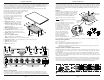
The RGB 440 may be mounted under, or on the side, of a table or desk using the included Under Desk
Mounting Kit, as shown in figure 1 and as detailed in the kit’s
documentation (68-461-01). Drill four pilot holes: front-to-
back, 2.5” apart, and side-to-side, 6.45” apart.
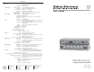
Descriptions of front and rear panel LEDs,
controls and connectors follow. The letters to
the left of the descriptions match the circled
letters in figure 2 below.
A. Power LED - On = power and video sync
pulses are present.
B. Audio input connector - 3.5 mm, stereo
jack (tip = L, ring = R, sleeve = ground).
C. Analog video input connector - Input
connector for MBC buffer, LBC, or MBC
cable from computer.
D. MBC Power output connector - Provides
power for MBC buffer if required.
E. Termination switch - Provides 75 ohms video
input termination if no local monitor is used.
F. H-Shift control - Shifts the image horizontally on
remote display device.
G. Sync processing DIP switches
Serr = Serration pulses enabled when up.
DDSP =Digital Display Sync Processing enabled when up.
H. Power input connector - The input voltage range is 12 to 24 volts AC or DC.
I. RGB BNC output connectors
J. Sync BNC output connectors
K. Audio output connector
Figure 2
Sync processing switches
Video projectors of different types or from different manufacturers may have slightly different sync pulse
requirements. Sync processing DIP switches on the RGB 440 front panel (G) enable the user to modify
output sync by enabling or disabling vertical sync serration pulses and enabling or disabling Digital Display
Installation and Operation
Extron • RGB 440 Interface • User’s Guide
Page 2
Remove 7
screws
PC board
(inside case)
Remove 2
connector
nuts
Slide cover
forward and
lift
Figure 3
Figure 1
Sync Processing (DDSP). The Sync processing switch module contains two DIP switches labeled SERR
(left switch) and DDSP (right switch). The Serr switch in the up position (enabled) will result in the removal
of serration pulses from the output composite sync signal (does not affect SOG, H or V outputs). The DDSP
switch in the up position (enabled) provides Digital Display Sync Processing, which may be required for
digital display devices which exhibit an unstable display. With DDSP enabled, the H Shift control (F) on the
front panel is defeated.
Jumpers
RGB analog signals passing through coax cables may
experience signal loss depending on the quality and
length of the cable. The signal loss occurs across all
frequencies but primarily higher frequencies. Boost/
peaking jumpers located inside the RGB 440
(figure 3) provide a way to compensate for these
losses.
CAUTION
Disconnect power before opening the
RGB 440.
To open the RGB 440, remove the mounting
brackets (if attached), remove six screws on
the sides (if not removed with the
mounting brackets), one screw on
the bottom, and two connector nuts
as shown in figure 3. There is one
jumper header for each of the RGB
color signals, J8 = red, J9 = green
and J10 = blue. Each header
provides three possible jumper
positions: unity gain (0.7V p-p),
0.8V p-p and 0.9V p-p.
Cable quality/length along
with video signal frequencies will
have a big impact on the jumper settings. Set up the jumpers just prior to securing the RGB 440 in place.
Jumper position guidelines
0.7V - Short cable runs
0.8V - Long cable runs, signal gain & peaking for all frequencies
0.9V - Long cable runs & high frequency video signals
High frequency signal boost and peaking compensates for high frequency signal loss due to cable
capacitance and bandwidth loss.
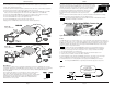
Using the captive screw audio output connector
The RGB 440 Interface has a single 3.5 mm, captive screw receptacle along the bottom right side of the rear
panel ((K) on figure 2). The audio receptacle has five contacts, and is labeled for left (L), right (R), polarity
(+/–), and ground.
A 3.5 mm captive screw connector (part number 10-319-10) is supplied with the RGB 440. The connector
must be wired to the output audio cables using the captive screws inside the connectors (figure 4A). The
audio connector is then plugged into the output connector on the rear panel. Figure 4C shows three methods
of wiring the output connector.
When making connections for the RGB 440 Interface from existing audio cables, see figure 4B. The round
audio connectors are shown with the top one (tip and sleeve only) for unbalanced audio and the bottom one
(tip, ring, and sleeve) for balanced audio. The ring, tip and sleeve markings are also used on the captive
screw connector diagrams in figure 4C. Use these examples as a guide for making audio cables.
Figure 4B
Tip
Sleeve
Ring (-)
Tip (+)
Sleeve
Figure 4C
Figure 4A
____ NO
SLEEVE
means NO CONNECTION. Wiring errors or plugging the audio connectors incorrectly
may damage the audio output circuits.