
user manual

Cable Connections
Extron • RGB 440 Interface • User’s Guide
Page 3
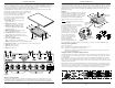
Installation of the RGB 440 using an MBC cable or an MBC buffer
For the following steps, use the diagram in figure 5A or 5B, whichever applies to your installation.
1. Turn off the computer and its monitor.
2. If desired, attach mounting brackets (Extron part #70-077-01, under-desk, or 70-077-02, through-desk).
3. Disconnect the local monitor cable from the computer and connect it to (A).
4. Connect the 9-pin connector from the MBC/MBC buffer to “Analog” on the RGB 440 (B). For an MBC
buffer, connect the small plug at the same end of the cable to "MBC Power" on the RGB 440.
5. Connect the remaining MBC/MBC buffer connector to the computer's video output connector (C).
6. Connect the PC audio output cable to the RGB 440 Audio input connector (D).
7. Connect the RGB 440 video output to the output device (E).
8. Connect the RGB 440 audio output to the audio output device (F).
9. Apply power to the RGB 440, the CPU and its monitor, and the output devices.
(A)
(B)
(C)
(D)
(E)
(F)
Figure 5A
—
Using an MBC cable.
(A)
(B)
(C)
(E)
(D)
(F)
Figure 5B
—
Using an MBC buffer.
Figure 6
DIP switches
Video projectors of different types or from different manufacturers may have slightly different sync pulse
requirements. DIP switches on the RGB 440 front panel enable the user to modify output sync (except SOG)
by enabling or disabling vertical sync serration pulses and enabling or disabling Digital Display Sync
Processing (DDSP).
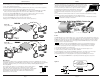
The front panel slide switches are shown in figure 6. The Serr switch, when on
(up position), will result in the removal of serration pulses from the output
composite sync signal. The DDSP switch, when on (up position), provides Digital
Display Sync Processing, which may be required for digital display devices
which exhibit an unstable display. The H Shift control is disabled when the
DDSP switch is in the on position.
Shields
Extron • RGB 440 Interface • User’s Guide
Page 4
Shield connections
If shielded, twisted pair wire such as that in Extron's Plenum Installation Cable
(figure 8) is being used with the RGB 440 captive screw connector, the shields
should be connected to connector pin 3 (the center pin) as shown in figure 7.
The wires that make up the braid shield (see figure 8) should be separated
and twisted together forming a large multi-strand wire, which is then
inserted into the receptacle side of the connector. Unused shielded,
twisted pair wire must be insulated and secured to prevent short
circuits.
The coax within the Plenum Installation Cable also contains a braid and foil shield which are normally
connected to ground through their individual connectors (BNC, RCA, etc.).
CAUTION
Exposed cable shields (braid, foil, etc.) are potential short circuits. Trim back and/or insulate
shields with electrical tape or heat shrink.
Figure 7
Figure 8
— Extron's Plenum Installation Cable
Power
The RGB 440 requires an external voltage source of 12 to 24 volts AC or DC (500 mA max). Polarity is not
an issue, even if the power source is a DC voltage. Simply insert the power plug into the connector labeled
POWER ((H) on figure 2) on the rear panel of the RGB 440. An optional 12 VDC external power supply is
available from Extron (Part #70-055-01). A power plug (included with RGB 440) must be soldered to the
power source wires. The procedure follows:
CAUTION
DO NOT connect the power plug/RGB 440 to a power source greater than 24 volts AC or
DC. To do so could cause serious damage to Extron equipment and/or User’s equipment.
To connect the power plug to the wires from the power source, see figure 9 and do the following:
1. Unscrew the black plastic cover from the plug.
2. Insert the wires from the power source through the tapered end of the black plastic cover.
3. Solder one wire to terminal 1, and the other wire to terminal 2.
4. Before plugging the power plug into the RGB 440, apply power to the voltage source and, using a
voltmeter, verify that the voltage at the plug is in the range of 12 to 24 volts AC or DC.
5. Reinstall the plastic cover on the plug and insert the plug into the RGB 440 power connector.
NOTE
The front panel POWER LED is on only when power and video sync pulses are present.
12 - 24 volts
AC or DC source
(Extron 12VDC power supply)
part # 70-055-01
Plastic cover
Figure 9