User’s Manual IRCM-DV+ Control Module Control Accessory www.extron.com Extron Electronics, USA Extron Electronics, Europe Extron Electronics, Asia Extron Electronics, Japan 1230 South Lewis Street Anaheim, CA 92805 USA 714.491.1500 Fax 714.491.1517 Beeldschermweg 6C 3821 AH Amersfoort The Netherlands +31.33.453.4040 Fax +31.33.453.4050 135 Joo Seng Road, #04-01 PM Industrial Building Singapore 368363 +65.6383.4400 Fax +65.6383.
Precautions Safety Instructions • English This symbol is intended to alert the user of important operating and maintenance (servicing) instructions in the literature provided with the equipment. This symbol is intended to alert the user of the presence of uninsulated dangerous voltage within the product's enclosure that may present a risk of electric shock. Caution Read Instructions • Read and understand all safety and operating instructions before using the equipment.
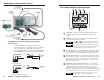
Quick Start Guide — IRCM-DV+ CAUTION Installation and service must be performed by authorized personnel only. See “UL Requirements”, page 2-2. The MediaLink™ Controller (MLC) to which the IRCM-DV+ is connected must have MLC firmware version 1.04 or higher in order to work with the IRCM-DV+. To set up the IRCM-DV+ you must use MediaLink Control Software version 2.0 or higher. Step 1 Turn the equipment off and disconnect the equipment from the power source.
Quick Start Guide — IRCM-DV+, cont’d Step 6 Table of Contents Chapter 1 • Introduction .......................................................... 1-1 Connect IR Emitters (one per each VCR, DVD player, or other device being controlled) to the MLC (see pages 2-5 and 2-6), and affix each emitter IR A Modulated IR Emitter Connect head near up to 4 IR Ground D Emitters the IR (max.). 110 feet (33.5 m) maximum receiver of MLC the device IR control port (VCR, DVD A B C D E IR player). About the IRCM-DV+ .......
Table of Contents, cont’d IRCM-DV+ 1 Chapter One Introduction About the IRCM-DV+ Features ii IRCM-DV+ • Table of Contents
Introduction About the IRCM-DV+ The Extron IRCM-DV+ is a hardwired remote control keypad designed for use with an Extron MediaLink Controller (MLC). Refer to the MediaLink Controllers User’s Manual for information on installing, operating, and setting up the controller. All setup and IR command learning must be done via RS-232. See chapter two and refer to the MediaLink Control Program or the MediaLink Controllers User’s Manual for details. The IRCM-DV+ fits into a four space high (2.8” H x 3.5” W, 7.
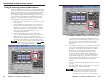
Installation and Operation CAUTION Installation and service must be performed by authorized personnel only. This product should be used with a UL approved electrical box. See “UL Requirements”, page 2-3. Rear Panel Connectors and Switches 1 1 A B C D E A B C D E The MLC to which the IRCM-DV+ is connected must have MLC firmware version 1.04 or higher in order to work with the IRCM-DV+. To set up the IRCM-DV+ you must use MediaLink Control Software version 2.0 or higher. UL Requirements 1.
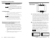
Installation and Operation, cont’d Cabling A B C D E For each control module to be connected to an MLC, set the rear panel DIP switches, then follow these steps: 1. If it wasn’t already done when the wall box was installed, cut a length of Extron Comm-Link cable to go between the MLC and the control module. 2. Using the following diagram as a guide, attach a 3.
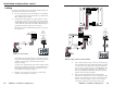
Installation and Operation, cont’d Front Panel Features and Operation To an MLS 306/506 Series Switcher or a 12VDC Power Supply 1 2 5 3 MLM Faceplate (rear) IRCM-DV+ Control Module Rear View MLC 206 Rear View DVD & VCR CONTROL DVD Tx VCR TITLE MENU ENTER TV/VCR TUNER Additional Control Module Rear View PREV/REW PLAY NEXT/FWD PAUSE IRCM-DV+ Front IR Emitter (Connect 2 per IRCM-DV+ and 1 per each additional IRCM.
Installation and Operation, cont’d Using IR Learning to Set Up the Buttons Before the IRCM’s buttons can control a VCR and a DVD player, you must connect the module and “teach” the MLC the control signals for each button (a process called “IR learning”).
Installation and Operation, cont’d commands are sent to all devices (VCR, DVD, projector) at the same time because the IR Emitters and/or IR Broadcaster share the MLC’s Display/Source Control IR port. As a result it is not possible to separately control two or more identical devices. 4B. If power is present at the MLC, at the control module, and at the VCR and DVD, but the VCR and/ or DVD does not respond when a button is pressed: • The MLC’s firmware may be too old.
Installation and Operation, cont’d IRCM-DV+ A Appendix A Specifications, Part Numbers, Accessories, and Dimensions Specifications Included Parts Accessories Cables Dimensions Index 2-12 IRCM-DV+ • Installation and Operation
Specifications, Part #s, Accessories, Dimensions Specifications Included Parts These items are included in each order for a control module: General Power ............................................. 12VDC from an MLC 206’s power supply or a System 5xi Temperature/humidity .............. Storage -40° to +158°F (-40° to +70°C) / 10% to 90%, non-condensing Operating +32° to +122°F (0° to +50°C) / 10% to 90%, non-condensing Rack mount ...................................
Specifications, Part Numbers, Accessories, cont’d Dimensions Index The following diagram has been reduced to fit on the page. All dimensions are given in inches. The symbol “ø“ indicates a diameter. M A MediaLink Control Program and IR learning 2-9 MediaLink Control Program, setup & troubleshooting 2-11 mounting 2-11 accessories A-3 C .160 MAX. EXTRUSION AROUND STUD ON FAR SIDE .112 THRU (4 PLCS MARKED B) cable, wiring 2-4 cables, part numbers A-3 cabling 2-4 Comm-Link cable conductor gauges A-3 .
Specifications, Part Numbers, Accessories, cont’d A-6 Control Modules • Specifications, Part #s, Dimensions