
User`s manual

IRCM-DV+ • Installation and Operation
IRCM-DV+ • Installation and Operation
Installation and Operation
2-32-2
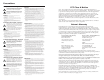
UL Requirements
1. This unit is not to be connected to a centralized DC power
source or used beyond its rated voltage range.
2. The IRCM-DV+ must be installed in a UL listed junction
box.
The UL approved electrical wall box (junction box) is not
included with the control module; the installer is
responsible for obtaining and installing the box.
3. The unit must be installed with accordance with the
National Electrical Code and with local electrical codes.
CAUTION
Installation and service must be performed by
authorized personnel only. This product should be
used with a UL approved electrical box. See
“UL Requirements”, page 2-3.
The MLC to which the IRCM-DV+ is connected must
have MLC firmware version 1.04 or higher in order to
work with the IRCM-DV+. To set up the IRCM-DV+
you must use MediaLink Control Software version
2.0 or higher.
ADBC EADBC E
1 1
2
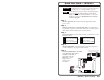
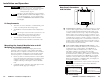
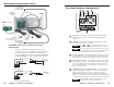
Rear Panel Connectors
and Switches
1
Communications connectors — Use these connectors to connect
control modules together and to connect them to the MLC and
to an optional IR Link infrared repeater. Both 3.5 mm, 5-pole
connectors function the same way, so they are interchangeable.
Install a captive screw connector (see pages 2-5 and 2-6) on one
end of an Extron Comm-Link cable and plug it into one of these
communications connectors. Install a connector onto the other
end of the cable and plug it into a communications connector on
another control module or an IR Link, or connect those wires to
the direct insertion IR/RCM captive screw connector of an MLC.
Do not install more than one IR Link.
2
Control module address identification DIP switches — Set
these switches to identify the address(es) of each module. Each
module must have a unique address. Each IRCM-DV+ is
assigned two addresses simultaneously: 1 and 2, or 3 and 4.
One address (address 2, for example) stores the VCR
information, the other address (address 1, for example) stores
the DVD information, and the pair of addresses (1 and 2 in this
example) are assigned together. If an IRCM-DV+ is assigned
addresses 1 and 2, another control module (a different type of
IRCM, an ACM module, or an RCM module, for example) can
be assigned to address 3 or to address 4.
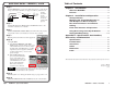
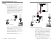
For the IRCM-DV+, switch 1’s position is not important.
Note the direction of the arrow on the switch. IRCM-DV+
address settings are shown below.
ON
12
ON
12
ON
12
ON
12
1 and 2 down (off) =
address 0, control module #1&2
1 up (on), 2 down (off) =
address 1, control module #1&2
1 down (off), 2 up (on) =
address 2, control module #3&4
1 up (on), 2 up (on) =
address 3, control module #3&4
or
DIP switch settings
Mounting the Control Module Into an AAP
Wallplate or Device Faceplate
The control module and any other adapter plates must be
attached to a device faceplate or AAP wallplate and cabled
before the device or wallplate is installed in a wall or furniture.
The screws needed for installing the control module are built
into its front panel, so no additional screws will be needed.
1. Before any cables are attached, insert the control module’s
screws through the holes in the device’s faceplate or AAP
wallplate. Secure the control module to the faceplate/
wallplate with the provided captive washers and #4-40
nuts.
2. Set the DIP switches, and follow steps 4 through 12 in the
Quick Start Guide (pages QS-1 and QS-2).