
User`s manual

IRCM-DV+ • Installation and Operation
IRCM-DV+ • Installation and Operation
Installation and Operation, cont’d
Cabling
For each control module to be connected to an MLC, set the rear
panel DIP switches, then follow these steps:
1. If it wasn’t already done when the wall box was installed,
cut a length of Extron Comm-Link cable to go between the
MLC and the control module.
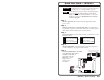
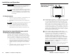
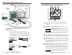
2. Using the following diagram as a guide, attach a 3.5 mm,
5-pole captive screw connector to the end of the cable that
will be plugged into the control module, and connect wires
on the other end of the cable to the MLC’s IR/RCM port (a
4-pole direct insertion captive screw connector).
Wire both ends of the cable identically (pin A to pin A, pin
B to pin B, etc.).
MLC
IR
/
RCM
port
ABCD
IR
/
RCM
Control
Module(s)
ABCDE
Control
Module
connector
C
C
+12VDC
Control signal (IRCM)
Ground ( )
B
B
A
A
MLC to a control module
MLC 206
Extron
MediaLink Controller
MLC 206
DISPLAY
POWER
VOLUME
MAX/
MIN
VCR DVD Laptop
Total
distance
from MLC:
150' (45.7 m)
max.
DVD & VCR CONTROL
PLAY NEXT/FWD PAUSE STOP
TUNER
Tx
PREV/REW
ENTER
TITLE MENU
TV/VCR
DVD VCR
Only three wires are required, but you can use four wires (A,
B, C, D) if an IR Link infrared repeater will be daisy chained
with the control modules. Refer to the IR Link User’s
Manual for details.
Connectors are included with each control module, but the
cable must be purchased separately. See the illustration on
the next page for reference, and see appendix A for cable
part numbers and conductor gauges.
3. Plug the 5-pole connector into either one of the control
module’s communications connectors.
2-52-4
ADBC E ADBC E
ON
12
ADBC EADBC E
MLC
IR
/
RCM
port
ABCD
IR
/
RCM
Control
Module
Control
Module
Control Module
Control Module
C
C
+12VDC
Control signal (IRCM)
Ground ( )
B
B
A
C
B
A
A
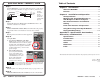
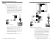
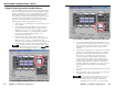
MLC to a daisy chain of control modules
MLC 206
Extron
MediaLink Controller
MLC 206
DISPLAY
POWER
VOLUME
MAX/
MIN
VCR DVD Laptop
Total
distance
from MLC:
150' (45.7 m)
max.
ROOM CONTROL
SCREEN POSITION LIGHTING
ON / OFF
DVD & VCR CONTROL
PLAY NEXT/FWD PAUSE STOP
TUNER
Tx
PREV/REW
ENTER
TITLE MENU
TV/VCR
DVD VCR
4. Cut a cable and attach 5-pole connectors to both ends of it
for each additional control module that will be connected
in a daisy chain. Wire both ends of the cable identically
(pin A to pin A, pin B to pin B, etc.). One IRCM-DV+ and
up to two other control modules in any combination of
other models (IRCM, ACM, RCM) can be daisy chained
together and connected to the MLC.
5. Plug one end of the cable into the control module’s
remaining communications connector, and plug the other
end into a communications connector on the next control
module. The following photo shows control modules
connected to an MLC in a typical daisy chain setup.