
User`s manual


SCP 150 • Installation and Operation
SCP 150 • Installation and Operation
Installation and Operation, cont’d
2-72-6
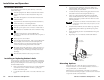
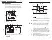
Cabling the Rear Panel
1
ON
234
J5
2
1
3
1
Panel address DIP switch — If using two SCPs, set DIP
switch 1 to assign a unique address to each panel. Set the
switch to Off to assign address 00 and On to assign address 01.
Switches 2 and 3 are not used.
The System 5 IP can support up to two SCPs.
The panels must each have a unique address.
DIP switch 4 is used to enable the RS-232/host port of
the SCP 150. Note: If the SCP is connected to the
System 5IP, set switch 4 to the “off” position.
2
CM/IR/SCP connectors — These two 5-pole captive screw
connectors function in exactly the same way and can be used
interchangeably. Connect one connector to a System 5 IP
switcher and the other to a second SCP, an Extron control
module (ACM, RCM, IRCM), or an Extron IR Link infrared
signal repeater.
Two SCPs, up to four control modules, and one IR Link can be
daisy-chained using these connectors. The maximum distance
between the System 5 IP and a connected device is 200' (61 m).
The switcher provides 12 VDC power to the SCP and any daisy-
chained control devices via these connectors, so no additional
power supply is required.
Wire the connectors as shown in the illustration on the next
page. The illustration is a guide; the SCPs, control modules, and
IR Link can be daisy-chained in combinations other than the one
shown.
3
Serial/host port — Use this 3-pole captive screw connector to
connect to your PC’s RS-232 port. Extron Simple Instruction Set
(SIS) commands can then be issued from the PC to monitor and
obtain information from the SCP. This port is also used for
uploading firmware to the SCP, if necessary. Refer to chapter 3,
Remote Communication, for further details.
Do not connect to this port if the SCP is being used with
the System 5IP.
ADBC EADBC E
Control
Module
SCP 150
IR Link
IRCM-DV+
Control Module
IR Link
SCP 150
DVD CONTROL
PLAY NEXT PAUSE STOP
Tx
REW
ENTER
TITLE
MENU
1
ON
234
J5
SCP 150
INPUT
1
INPUT
2
INPUT
3
INPUT
4
INPUT
5
PROJECTOR
ON
PROJECTOR
OFF
FUNCTION
BUTTON
PROJECTOR
LIGHTS
ON
IR
LIGHTS
OFF
PC
VOLUME
SIGNAL
IR LINK
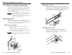
ADBC E
D
B
A
System 5 IP
Rear Port
D
C
C
E
Modulated IR (IR Link)
SCP Communication (IR)
+12VDC
Control signal (IRCM)
Ground ( )
D
B
B
E
A
A
D
C
C
Modulated IR (IR Link)
IR Link
+12VDC
+12VDC
Control signal (IRCM)
Ground ( )
Ground ( )
D
B
B
A
A