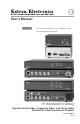
User’s Manual C Do not connect this device to a computer data or telecommunications network TP Receivers Family HIgh Resolution Video, Composite Video, and Stereo Audio Twisted Pair Cable Transmission Products 68-547-02 Rev.
Precautions Safety Instructions • English This symbol is intended to alert the user of important operating and maintenance (servicing) instructions in the literature provided with the equipment. This symbol is intended to alert the user of the presence of uninsulated dangerous voltage within the product’s enclosure that may present a risk of electric shock. Caution Read Instructions • Read and understand all safety and operating instructions before using the equipment.
Precautions, cont’d 安全须知 • 中文 警告 这个符号提示用户该设备用户手册中 有重要的操作和维护说明。 电源 • 该 设 备 只 能 使 用 产 品 上 标 明 的 电 源 。 设 备 必须使用有地线的供电系统供电。 第三条线 (地线)是安全设施,不能不用或跳过。 这个符号警告用户该设备机壳内有暴 拔掉电源 • 为安全地从设备拔掉电源,请拔掉所有设备后 或桌面电源的电源线,或任何接到市电系统的电源线。 露的危险电压,有触电危险。 电源线保护 • 妥善布线, 避免被踩踏,或重物挤压。 注意 阅读说明书 • 用 户 使 用 该 设 备 前 必 须 阅 读 并 理 解所有安全和使用说明。 保存说明书 • 用户应保存安全说明书以备将来使 用。 遵守警告 • 用户应遵守产品和用户指南上的所有安 全和操作说明。 维护 • 所有维修必须由认证的维修人员进行。 设备内部 没有用户可以更换的零件。为避免出现触电危险不要自 己试图打开设备盖子维修该设备。 通风孔 • 有些设备机壳上有通风槽或孔,它们是用来防止 机内敏感元件过热。 不要用任何东西挡住通风孔。 锂电池 • 不正确的更换电池会有
ii TP Receivers
Table of Contents Chapter One • Introduction ................................................... 1-1 About the TP Receivers ...................................................... 1-2 Features ..................................................................................... 1-3 TP R BNC A receiver .............................................................. 1-3 TP R BNC AV receiver ............................................................ 1-4 TP R 15HD A receiver ..................................
Table of Contents, cont’d Appendix • Specifications, Accessories, and Part Numbers .............................................................................................. A-1 Specifications . ........................................................................ A-2 Included Parts ......................................................................... A-6 Extron Accessories ............................................................... A-6 Cables/Adapters ........................................
TP Receivers 1 Chapter One Introduction About the TP Receivers Features
Introduction, Introductioncont’d About the TP Receivers The TP R BNC A, TP R BNC AV and TP R 15HD are Extron Twisted Pair (TP) receivers that receive transmissions of RGB video, component video, S-video, composite video, and stereo audio over Extron Enhanced Skew-Free™ A/V UTP cable or standard Category (CAT) 5 unshielded twisted pair (UTP), shielded twisted pair (STP), or foil shielded twisted pair (FTP) cable. Standard transmission distance is shown in the tables below.
The TP receivers only receive signals transmitted by Extron TP transmitters. This user manual documents installation, features, and operation of the TP receivers only. For information about the TP transmitters, refer to the TP Transmitters Family User’s Manual, TP T 15HD 45 and TP T A 45 Manual, or the VTT001/TR001 Transmitter and Receiver Manual, as applicable, which accompanies the transmitters.
Introduction, cont’d TP R BNC AV receiver The TP R BNC AV receiver has the following features: Video output — Provides RGBHV, RGBS, or RGsB video on 5 BNC connectors, and composite video on 1 BNC connector. RJ-45 connector — Allows attachment to an Extron TP transmitter. One connector is for computer input, and one is for A/V input. Cable length compensation — Allows you to select whether to compensate for long cable runs automatically or manually.
TP R 15HD A receiver The TP R 15HD A receiver has the following features: Video output — Provides RGBHV, RGBS, and RGsB on a 15-pin HD connector. With an optional SY 15 HD-RGBHV cable, the receiver can output component video, S-video, or composite video. RJ-45 connector — Allows attachment to an Extron TP transmitter.
Introduction, cont’d This page intentionally left blank.
TP Receivers 2 Chapter Two Installation and Operation Installation Overview Front Panel Controls and Indicators Troubleshooting
Installation Installation and andOperation Operation, cont’d Installation Overview To install and set up a TP receiver and the associated TP transmitter(s) for operation, perform the following steps: 1 Disconnect power from all of the equipment, including the video source(s) (such as computers or DVD players), the transmitter, the receiver, and the output display(s).
N The following transmitters are compatible with the TP R 15HD A, TP R BNC A and TP R BNC AV receivers: TP T 15HD 45, TP T A 45, TP T 15HD A, TP T 15HD AV, TP T 468 N All TP transmitters include a 15V or 12V external power supply. The transmitters (with the exception of the TP T 15HD 45 and TP T A 45) also receive power from the associated Extron TP receiver(s) (with the exception of the TP R 15HD A) via the TP cable.
Installation and Operation, cont’d Video jumpers The TP R BNC A and TP R BNC AV receivers can be configured to receive component video, S-video, or composite video. N 1. The receivers are factory configured for RGB video. To receive any other type of video, reconfigure the jumpers. Remove the three screws on each side and the two screws on top of the cover (figure 2-1). Remove 8 Screws A 1.
5. 6. Locate J3 on the RGB video printed circuit board. See figure 2-1. a. For RGB video, ensure that pin 2 is jumpered to pin 3. b. For any other video format, ensure that pin 1 is jumpered to pin 2. Reinstall the video board, replace the cover, and reinstall the screws and BNC connector hex nuts. The TP R 15HD A receiver can be configured to receive component video, S-video, or composite video.
Installation and Operation, cont’d 1. Remove three screws on each side and one or two screws on top of the cover (figure 2-2). Remove 8 Screws A 1.
Mounting the receiver UL guidelines for rack mounting The following Underwriters Laboratories (UL) guidelines are relevant to the safe installation of the TP Receivers in a rack: 1. Elevated operating ambient temperature — If the unit is installed in a closed or multi-unit rack assembly, the operating ambient temperature of the rack environment may be greater than room ambient temperature.
Installation and Operation, cont’d Rack mounting (TP R BNC A, TP R BNC AV, TP R 15HD A) TP R BNC A, TP R BNC AV, or TP R 15HD AV — For optional rack mounting, mount the receiver on a 9.5" deep 1U Universal Rack Shelf (Extron part #60-190-01) (figure 2-3). The TP R BNC A and TP R BNC AV mount on the left or right side of the rack. The TP R 15HD A mounts in one of eight locations on the rack.
TP R 15HD A only — For optional rack mounting, mount the receiver on a VersaTools 3.5" deep 1U Rack Shelf (Extron part #60-190-20) (figure 2-4). The TP R 15HD A mounts in one of four locations on the rack.
Installation and Operation, cont’d All models except the TP R 15HD A can be mounted through a table or podium using an Extron Through-Desk Mounting Kit for 1/4 or 1/2 Rack Width Products (part #70-077-02). Furniture mount the receiver as follows: Attach the mounting brackets to the receiver with the machine screws provided (figure 2-5). R L V IO D U A A L B R 15 ER DC W POV .5A 1.
7. For under-surface mounting, align the mounting screws with the slots in the brackets and place the receiver against the surface, with the screws through the bracket slots. 8. For under-surface mounting, slide the receiver slightly forward or back, then tighten all four screws to secure the switcher in place.
Installation and Operation, cont’d Rear panel features and cabling 6 7 VIDEO 8 A-V AUDIO A R L B 9 100-240V R A-V INPUT AUDIO A R R G B H/HV RGB OUTPUT AUDIO L B V 50/60 Hz 1 3 5 7 8 1 3 5 7 8 A R G B H/HV RGB OUTPUT TP R BNC AV 9 AUDIO R RGB INPUT R L SOG C SYNC RGB INPUT 0.3A L SOG C SYNC 2 POWER 15V .5A DC B L R L V TP R BNC A 4 RGB AV INPUT 8 L AUDIO 5 R C SYNC SOG C VIDEO N/C 1 9 POWER 15V .
Output cabling Computer video The TP R BNC A, TP R BNC AV and TP R 15HD A receive and output RGB video. These receivers can also receive component video, S-video, or composite video and output them on the R, G, and B signal lines. Reception of component video, S-video, or composite video requires an internal jumper (TP R BNC AV and TP R BNC) or external DIP switch (TP R 15HD A) be repositioned. See Video jumpers or Video DIP switch in this chapter.
Installation and Operation, cont’d d 10 5 15 1 11 Female RGB Output 15HD (TP R 15HD A) — Connect the desired video output device to the rear panel output 15HD connector. Refer to the table below for the video signal connections. Pins 13 and 14 are for sync only.
Audio All Extron TP receivers receive and output stereo audio. All receivers except the TP R 15HD A output the audio on both left and right RCA connectors and on 3.5 mm, 5-pole captive screw connectors. The TP R 15HD A outputs audio on the captive screw connector only. g Stereo audio output connectors — Connect left and right stereo audio cables between these rear panel RCA connectors and the output device stereo audio inputs.
Installation and Operation, cont’d TP R BNC A — Wire the external 15 V power supply into this 3-pole captive screw connector (figure 2-9) and plug the connector into the receiver. The power supply is included with the unit. TP R BNC A N/C TP R 15HD A Ridges Smooth A SECTION A–A 3/16” (5 mm) Max.
Enhanced Skew-free A/V cable is not recommended for Ethernet/LAN applications. N This cable is specially designed for compatibility with Extron’s Twisted Pair products, wired using the TIA/EIA 568 A standard. The green, brown, and blue pairs of this cable have virtually identical lengths, and should be used to transmit the RGB signals. The orange pair of this cable has a different length and should not be used to transmit RGB signals.
Installation and Operation, cont’d Skew exists between pairs when the physical length of one wire pair is different from another. As the transmission cable length increases, the amount of skew increases. Skew affects the displayed image when the differential length between wire pairs exceeds 2 feet, causing the timing of red, green, and blue video signals to appear out of alignment (horizontal registration errors).
Front Panel Controls and Indicators The TP R BNC A and TP R BNC AV have similar controls and indicators (figure 2-12). The TP R 15HD A has a reduced set of controls (figure 2-13).
Installation and Operation, cont’d • The transmitter is receiving power from the receiver, a local monitor is connected to the transmitter, and the receiver output is connected to a device that provides a reference ground. • The receiver is connected through a TP switcher to a device that provides a reference ground. b Manual/Auto switch (TP R BNC A and TP R BNC AV) — With this switch in the Auto position, the receiver automatically adjusts level and peaking to compensate for long cable runs.
N The TP T 15HD 45 and TP T A 45 do not have the DDSP feature. 7. The transmission distance may be too far for remote power. Try connecting a local 15 V power supply to the transmitter. 8. The transmission distance may be too short. Ensure the UTP cable is at least 50 feet long. 9. If the Manual/Auto switch is in the manual position, ensure the receiver level controls are not set too high. Too much level and peaking can cause display problems. 10.
Installation and Operation, cont’d If the receiver Manual/Auto LED flashes 2-22 1. The transmission distance may be too far for remote power. Connect a local 15 V power supply to the transmitter. 2. Check the RJ-45 connector for a loose connection.
TP Receivers A Appendix Specifications, Accessories, and Part Numbers Specifications Included Parts Accessories Cables/Adapters
Specifications, Accessories, Specifications, Accessories, and and Part Part Numbers Numbers cont’d Specifications Video Number/signal type �������������������� 1 or 2 sets of proprietary analog signals Connectors ������������������������������������ 1 or 2 shielded RJ-45 female Video input — refer to the TP Transmitters Family User’s Manual, part #68‑546‑02 Video output Number/signal type TP R BNC A ������������������������ 1 analog RGBHV, RGBS, RGsB, component video, or S-video; or 1 S-video and 1 NTSC/
Audio Number/signal type ��������������������� Connectors ������������������������������������� Frequency response ���������������������� THD + Noise ���������������������������������� S/N �������������������������������������������������� Crosstalk ����������������������������������������� Stereo channel separation ������������ CMRR ���������������������������������������������� 1 or 2 sets of analog proprietary signals 1 or 2 shielded RJ-45 female 20 Hz to 20 kHz, >±0.05 dB 0.03% @ 1 kHz, 0.
Specifications, Accessories, and Part Numbers cont’d Temperature/humidity ���������������� Storage -40° to +158°F (-40° to +70°C) / 10% to 90%, noncondensing Operating +32° to +122°F (0° to +50°C) / 10% to 90%, noncondensing Cooling ������������������������������������������� Convection, no vents Mounting Rack mount TP R 15HD A �������������� Yes, with optional 1U, 9.5" deep rack shelf, part #60-190-01 (RSU 129) or #60-604-01 (RSB 129); or 1U, 3.
Product weight TP R BNC A ������������������������ TP R BNC AV ��������������������� TP R 15HD A ���������������������� Shipping weight TP R BNC A ������������������������ TP R BNC AV ��������������������� TP R 15HD A ���������������������� Vibration ���������������������������������������� Regulatory Compliance Safety ����������������������������������� EMI/EMC �������������������������� MTBF ����������������������������������������������� Warranty ���������������������������������������� 1.6 lbs (0.
Specifications, Accessories, and Part Numbers cont’d Included Parts These items are included in each order for a specific TP receiver: Included parts Part number All TP Receiver User's Manual Captive screw connector, 5 pole, 3.5 mm (1 or 2) TP R BNC A 100-457-01 60-351-02 Single output external power supply, 15 V, 0.8 A 70-776-01 Captive screw connector, 3 pole, 3.5 mm 100-456-01 TP R 15HD A Single output external power supply, 15 V, 0.
Cables/Adapters N Enhanced Skew-Free A/V UTP cables are not recommended for Ethernet/LAN applications.
Specifications, Accessories, and Part Numbers cont’d Video cables and adapters A-8 Part number MHR-5 BNC/3 (3 feet/0.9 meters) 26-260-15 MHR-5 BNC/6 (6 feet/1.8 meters) 26-260-01 MHR-5 BNC/12 (12 feet/3.7 meters) 26-260-02 MHR-4 BNC/3 (3 feet/0.9 meters) 26-210-01 MHR-4 BNC/6 (6 feet/1.8 meters) 26-210-02 MHR-4 BNC/12 (12 feet/3.7 meters) 26-210-03 MHR-2 SVM-M/6 SVHS (6 feet/1.8 meters) 26-316-02 MHR-2 SVM-M/12 SVHS (12 feet/3.
Extron’s Warranty Extron Electronics warrants this product against defects in materials and workmanship for a period of three years from the date of purchase.
Extron USA - West Headquarters +800.633.9876 Inside USA / Canada Only +1.714.491.1500 +1.714.491.1517 FAX Extron USA - East Extron Europe Extron Asia Extron Japan Extron China Extron Middle East +800.633.9876 +800.3987.6673 +800.7339.8766 +81.3.3511.7655 +81.3.3511.7656 FAX +400.883.1568 +971.4.2991800 +971.4.2991880 FAX +1.919.863.1794 +1.919.863.1797 FAX +31.33.453.4040 +31.33.453.4050 FAX +65.6383.4400 +65.6383.