
Setup guide


1
XTP SR HDMI • Setup Guide
The Extron XTP SR HDMI is an XTP receiver
that scales HDMI, DVI, RGB, HD component
video, and standard denition video to the
optimal output resolution. This guide provides
instructions for an experienced installer to
install and connect the XTP SR HDMI scaling
receiver.
Installation
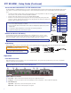
Rear Panel Features
Power and Throughput Connections Output Connections Control Connections and Reset
a
DC power connector and power LED
b
XTP input connector and Sig and Link LEDs
c
LAN connector and LEDs
d
RS-232/IR Over XTP connector
e
HDMI output connector and
corresponding HDMI audio switch
f
Analog audio output connector
g
S/PDIF digital audio output connector
h
Relay connectors
i
Remote RS-232 connector
j
Reset button
Mounting and Cabling
Step 1 — Mounting
Turn off or disconnect all equipment power sources and mount the XTP SR HDMI as required.
Step 2 — Connecting Outputs
a. Connect a digital video display to the female HDMI connector (see e above).
b. Connect a balanced or unbalanced, stereo or mono audio output device to the 3.5 mm, 5-pole captive screw connector (see f above) for
2-channel stereo analog audio (for wiring details, see Audio Wiring on page 2).
c. Connect an audio device to the female orange RCA connector for digital S/PDIF audio output (see g above).
Step 3 — Connecting Throughput Devices
a. Connect a twisted pair cable between the XTP input connector of the XTP SR HDMI (see b above) and the XTP output connector on an XTP
transmitter or XTP matrix switcher. For cable recommendations, see Twisted Pair Recommendations for XTP Communication on page 2.
ATTENTION: Do not connect this connector to a computer data or telecommunications network.
Sig LED — Lights when it receives an active XTP input signal from the transmitter or matrix switcher.
Link LED — Lights when a valid XTP link is established.
b. To pass bidirectional serial, infrared, or other control signals, connect a control device or a device to be controlled to the RS-232 and IR Over
XTP connector (see d above).
NOTE: RS-232 and IR data can be transmitted simultaneously (see RS-232 and IR Over XTP Wiring on page 2).
d. Connect a host device or control LAN or WAN to the LAN RJ-45 connector for pass-through 10/100Base-T Ethernet communication
(see c above). This is an Ethernet pass-through port with LEDs to indicate link and activity status.
Step 4 — Connecting Control Devices
a. Connect a host device, such as a computer, to the female mini-USB B port on the front panel to congure the receiver or update rmware
(see b on page 2).
b. Connect equipment that can be controlled via momentary or latching contact, such as projector screens or lifts, to these normally open relays
(see h above). Do not exceed 24 V at 1 A for each port.
c. For serial RS-232 control of the receiver, connect a host device to the Remote RS-232 3.5 mm, 3-pole captive screw connector (see i above).
Step 5 — Connecting Power
Power the XTP SR HDMI in one of the following methods:
• Connect the provided external 12 V, 1.0 A power supply to the 2-pole captive screw connector for local power (see a above).
• Connect an XTP Power Injector to the XTP connection between the XTP SR HDMI and a locally powered XTP transmitter or XTP matrix
switcher (see the XTP Power Injector User Guide for more details).
• Connect the XTP SR HDMI to an XTP matrix switcher and enable the remote power feature on the XTP matrix switcher.
ATTENTION: XTP remote power is intended for indoor use only. No part of the network that uses XTP remote power should be routed
outdoors.
LAN
SIG LINK
XTP IN
POWER
12V
HDMI
1.0 A MAX
Rx GTx
RS-232 IR
RxTx
−+−+
LR
1
2
AUDIO
OFF
ON
AUDIO
S/PDIF
RESET
RS-232
Tx Rx G
OUTPUTS
OVER XTP RELAYS REMOTE
bc defghia j