
Setup guide


2
XTP SR HDMI • Setup Guide (Continued)
Twisted Pair Recommendations for XTP Communication
The XTP SR HDMI is compatible with CAT 5e, 6, 6a, and 7 shielded twisted pair (F/UTP, SF/UTP, and S/FTP) and unshielded twisted pair (U/UTP)
cable. Extron recommends using the following practices to achieve full transmission distances up to 330 feet (100 m) and reduce transmission
errors.
• Use Extron XTP DTP 24 SF/UTP cable for the best performance. If not using XTP DTP 24 cable, at a minimum, Extron recommends 23 AWG,
solid conductor, STP cable with a minimum bandwidth of 400 MHz.
• Terminate cables with shielded connectors to the TIA/EIA-T568B standard.
• Limit the use of more than two pass-through points, which may include patch points, punch down
connectors, couplers, and power injectors. If these pass-through points are required, use CAT 6 or 6a
shielded couplers and punch down connectors.
NOTE: When using CAT 5e or CAT 6 cable in bundles or conduits, consider the following:
• Do not exceed 40% ll capacity in conduits.
• Do not comb the cable for the rst 20 m, where cables are straightened, aligned, and secured in
tight bundles.
• Loosely place cables and limit the use of tie wraps or hook and loop fasteners.
• Separate twisted pair cables from AC power cables.
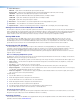
RS-232 and IR Over XTP Wiring
To pass bidirectional serial command signals between XTP-compatible devices, connect a control
device to the three leftmost poles (Tx, Rx, and G) of the 5-pole captive screw connector. To transmit
and receive IR signals, connect a control device to the three rightmost poles (G, Tx, and Rx).
NOTE: RS-232 and IR data can be transmitted or received simultaneously.
Audio Wiring
Wire the audio output connector as shown to the right. Use the supplied tie-wrap to strap the audio cable to the extended tail of the connector.
ATTENTION: For unbalanced outputs, do
not connect wires to the “-” poles.
NOTE: The length of exposed wires is critical.
The ideal length is 3/16 inch (5 mm).
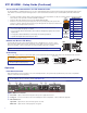
Operation
Front Panel Overview
After all transmitters and connected devices are connected and powered on, the system is fully operational. If any issues arise, verify that the
cables are routed and connected properly.
NOTE: Use the Extron XTP System Configuration software or SIS commands to configure the XTP SR HDMI (for more details, see the
XTP SR HDMI User Guide on the Extron website, www.extron.com).
XTP
HDCP
SIGNAL
AUDIO
HDMI
HBR
S/PDIF
BITSTREAM
ANALOG
LPCM
XTP SR HDMI
MENU ENTER
ADJUST
CONFIG
ADJ
X
X
X
XTP
U
ST
Front Panel
cd ef ga b
Figure 1. Front Panel Features
a Power LED — Lights on the front and rear panels when power is applied to the device.
b Config port — Connect a host device to the mini USB B port for device conguration, control, and rmware upgrades.
c XTP LED indicators —
Signal LED — Lights when an active XTP video signal is received.
HDCP LED — Lights when the XTP input signal is encrypted.
Tx/Rx
Pins
RxTx
RS-232
RxTx
TxRx
RxTx
IR Device
RS-232 De
vice
G
G
G
IR
TIA/EIA-T568B
Pin Wire Color
1 White-orange
2 Orange
3 White-green
4 Blue
5 White-blue
6 Green
7 White-brown
8 Brown
12345678
RJ-45
Connector
Insert Twisted
Pair Wires
Pins:
Pin
1
2
3
4
5
6
7
8
Wire color
White-green
Green
White-orange
Blue
White-blue
Orange
White-brown
Brown
Wire color
T568A T568B
White-orange
Orange
White-green
Blue
White-blue
Green
White-brown
Brown
Do not tin the wires!
Balanced Audio Output
Tip
Ring
Tip
Ring
Sleeves
Unbalanced Audio Output
Tip
No Ground Here
No Ground Here
Tip
Sleeves
LR
LR