User Guide XTP Extenders XTP T HDMI XTP R HDMI XTP HDMI Transmitter and Receiver 68-1723-01 Rev.
Safety Instructions • English WARNING: This symbol, , when used on the product, is intended to alert the user of the presence of uninsulated dangerous voltage within the product’s enclosure that may present a risk of electric shock. Chinese Simplified(简体中文) 警告: 产品上的这个标志意在警告用户该产品机壳内有暴露的危险 电压,有触电危险。 注 意: ATTENTION: This symbol, , when used on the product, is intended to alert the user of important operating and maintenance (servicing) instructions in the literature provided with the equipment.
FCC Class A Notice This equipment has been tested and found to comply with the limits for a Class A digital device, pursuant to part 15 of the FCC rules. The Class A limits provide reasonable protection against harmful interference when the equipment is operated in a commercial environment. This equipment generates, uses, and can radiate radio frequency energy and, if not installed and used in accordance with the instruction manual, may cause harmful interference to radio communications.
Conventions Used in this Guide Notifications The following notifications are used in this guide: WARNING: A warning indicates a situation that has the potential to result in death or severe injury. ATTENTION: Attention indicates a situation that may damage or destroy the product or associated equipment. NOTE: A note draws attention to important information. TIP: A tip provides a suggestion to make working with the application easier.
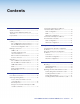
Contents Introduction..................................................... 1 About This Guide................................................. 1 About the XTP HDMI Transmitter and Receiver............................................................. 1 Key Features....................................................... 2 Installation and Operation............................... 4 Cabling................................................................ 4 XTP T HDMI Rear Panel Connectors................
XTP T HDMI Transmitter and XTP R HDMI Receiver • Contents v
Introduction This section contains general information about this guide and the Extron XTP T HDMI transmitter and XTP R HDMI receiver. Topics in this section include: • About This Guide • About the XTP HDMI Transmitter and Receiver • Key Features About This Guide This guide contains installation, operation, control, and reference information for the XTP T HDMI transmitter and the XTP R HDMI receiver.
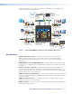
The following diagram shows some ways the XTP T HDMI and the XTP R HDMI can be integrated in an XTP matrix application.
EDID Minder — Automatically manages EDID communication between connected devices. It ensures that all sources power up properly and reliably outputs content for display. Key Minder — Authenticates and maintains continuous HDCP encryption between input and output devices to ensure quick and reliable switching in professional AV environments, while enabling simultaneous distribution of a single source signal to one or more displays.
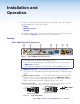
Installation and Operation This section contains the installation procedures for and operation of the XTP T HDMI and the XTP R HDMI. Topics in this section include: • Cabling • Making Connections • Operation XTP HDMI transmitters and receivers can be mounted in a rack or under a desk or placed on a tabletop (see Mounting on page 29 for more mounting details). Cabling XTP T HDMI Rear Panel Connectors g a b INPUTS POWER 12V 1.0 A MAX AUDIO ON HDMI Figure 2.
d RS-232 Over XTP port — To pass bidirectional serial, Infrared, or other control signals between XTP-compatible devices, connect a control device to the 5-pole captive screw connector. The port includes only the 3 poles labeled “RS-232.” RS-232 IR Over XTP port — To enable the ability to transmit and receive IR signals (up to 40 kHz), connect a control device to the 5-pole captive screw connector. This port includes only the 2 poles labeled “IR” and shares the ground pole with the RS-232 port.
XTP R HDMI Rear Panel Connectors h a SIG POWER 12V 1.0 A MAX LINK c OVER XTP RS-232 XTP IN Figure 4. a b LAN Tx Rx IR G Tx Rx d OUTPUTS AUDIO AUDIO ON OFF e f g HDMI L R + - + - RELAYS 1 2 RESET S/PDIF XTP R HDMI Connectors XTP connector — Connect a twisted pair cable to the RJ-45 connector labeled XTP In on the receiver and to an XTP output port on another XTP device to receive all signals (see TP Cable Termination and Recommendations on page 9).
e Analog audio output — Connect a balanced or unbalanced, stereo or mono audio output device to the 3.5 mm, 5-pole captive screw connector for 2-channel stereo analog audio output. If the device is receiving 2-channel LPCM embedded on the HDMI input signal and digital is the selected audio input format, it is extracted and converted to a stereo analog signal. No Ground Here L L R Tip Sleeves Tip R Tip Ring Sleeves Tip Ring Do not tin the wires! No Ground Here Balanced Audio Output Figure 5.
Making Connections HDMI LockIt Use an Extron LockIt Lacing Bracket to secure an HDMI cable to each device as follows: 1. Plug the HDMI cable into the panel connection. 3 4 3 2 5 1 Figure 7. Installing the LockIt Lacing Bracket 2. Loosen the HDMI connection mounting screw from the panel enough to allow the LockIt lacing bracket to be placed over it. The screw does not have to be removed. 3.
TP Cable Termination and Recommendations Use the following pin configurations for twisted pair cables.
RS-232 and IR Communication The RS-232 and IR Over XTP connector is for pass-through transmission of serial signals, such as projector control signals, and Infrared data (see figure 9 below for an example of how to wire the connector). Custom IR Device Rx Tx G Tx Rx Tx Rx RS-232 G IR Tx/Rx Pins Tx Rx G RS-232 Device Figure 9. Wiring the RS-232 and IR Connector Cross the Tx and Rx lines once between the source and target. ATTENTION: The length of exposed wires is critical.
Power Connection Apply power to the transmitter or receiver locally with the provided power supply or remotely with a power injector or a matrix switcher. ATTENTION: XTP remote power is intended for indoor use only. No part of the network that uses XTP remote power should be routed outdoors. Local power 2-Pole Captive Screw Connector Tie Wrap 3/16” (5 mm) Max. SECTION A–A Smooth Ridges A A Power Supply Output Cord Figure 10.
Remote power The XTP HDMI transmitter and receiver can be powered remotely through an XTP Power Injector or through an XTP matrix switcher. ATTENTION: XTP remote power is intended for indoor use only. No part of the network that uses XTP remote power should be routed outdoors.
Operation After all transmitters, all receivers, and their connected devices are powered up, the system is fully operational. If any problems are encountered, verify that the cables are routed and connected properly. If problems persist, call the Extron S3 Sales & Technical Support Hotline. See the contact numbers on the last page of this guide for the nearest Extron office.
c Audio indicators HBR LED — Lights when the input audio signal is high bit rate audio. Bitstream LED — Lights when the input audio signal is a Dolby® Digital, DTS® audio format and 2-channel Dolby. LPCM LED — Lights when the input audio signal is LPCM-2Ch. HDMI LED — Lights when the input audio format is multi-channel, LPCM-2Ch, or Hi-Def audio. S/PDIF LED — Lights when the input audio format is multi-channel (except HBR), or LPCM-2Ch, Analog LED — Lights when the input audio format is LPCM-2Ch.
Audio Output Overview By default, the XTP HDMI transmitter prioritizes embedded digital audio over analog audio. Use SIS commands or the XTP System Configuration Software to manually select the audio input (see SIS Configuration and Control on page 16 or the XTP System Configuration Software on page 23). Audio Output Audio Input Format HDMI S/PDIF Analog LPCM up to 7.1, 24 bit, 192 kHz X X X Multi-channel PCM X Dolby Digital 2/0 X X Dolby Digital 2/0 Surround X X Dolby Digital 5.
SIS Configuration and Control The XTP T HDMI and XTP R HDMI can be configured and controlled using Extron Simple Instruction Set (SIS) commands or the XTP System Configuration Software (see XTP System Configuration Software on page 23). This section contains basic SIS communication details and SIS commands and responses when connected directly to an XTP T HDMI or XTP R HDMI.
Error Responses When the XTP T HDMI or the XTP R HDMI receives an SIS command and determines that it is valid, it performs the command and sends the corresponding response to the host device. If the command is determined invalid or contains invalid parameters, the transmitter or receiver returns an error response to the host.
X2@ = EDID Emulation See the table below EDID Emulation Table (where X2@ = the SIS value) SIS Value Resolution Refresh Rate (Hz) Output 1 Receiver output 2 Transmitter loop-through output 3 800x600 60 4 1024x768 60 DVI 5 1280x720 with 2-ch audio* 60 HDMI 6 1280x768 60 DVI 7 1280x800 60 DVI 8 1280x1024 60 DVI 9 1360x768 60 DVI 10 1366x768 60 DVI 11 1400x1050 60 DVI 12 1440x900 60 DVI 13 1600x1200 60 DVI 14 1680x1050 60 DVI 15 1920x1080 with 2-ch audi
Command and Response Tables for Transmitter SIS Commands The following commands are for direct connections to the XTP T HDMI (see to the XTP matrix switcher user guide for commands that can be sent from the matrix to endpoints). Command ASCII Command Response Additional Description Set input audio selection E I X& AFMT} AfmtI X&] Set which audio input signal the transmitter will send. Auto will prioritize digital over analog audio.
Command ASCII Command Response Additional Description Set EDID information E A X2@ EDID} EdidA X2@] Set the EDID resolution and refresh rate. View EDID information E AEDID} EdidA X2@] View the EDID resolution and refresh rate. HDCP authorized device on E E1HDCP} HdcpE1] Set the transmitter as an HDCP authorized device. HDCP authorized device off E E0HDCP} HdcpE0] Set the transmitter as not an HDCP authorized device.
Command and Response Tables for Receiver SIS Commands The following commands are for direct connection to the XTP R HDMI (refer to the XTP matrix switcher user guide for commands that can be sent from the matrix to endpoints). Command ASCII Command Response Additional Description Set volume X1! V Vol X1!] Set the output volume to X1!. Increment volume +V Vol X1!] Increase the audio volume. Decrement volume -V Vol X1!] Decrease the audio volume.
Command ASCII Command Response Additional Description View input signal presence 0LS Frq X1^] View the input signal presence. Query HDCP output E OHDCP} HdcpO X(] Query the HDCP status. Query firmware version Q x.xx ] Query the firmware version. Query full firmware version *Q x.xx.xxxx ] Query the full firmware version. Query part number 60-1043-13] Query the device part number.
XTP System Configuration Software This section contains installation and configuration procedures for the XTP System Configuration Software to configure and control XTP HDMI transmitters and receivers. Topics in this section include: • Installing the XTP System Configuration Software • Using the XTP System Configuration Software The XTP System Configuration Software is convenient, user-friendly control software for configuring an XTP system or individual XTP devices.
To download the software from the website: Figure 15. Extron Website Download Page 1. On the Extron website, click the Download tab. 2. From the left sidebar, click the Software link. 3. Navigate to XTP System Configuration. 4. Click the Download link to the right of the desired device. 5. Submit any required information to start the download. Note where the file is saved. 6. Open the executable (.exe) file from the save location. 7. Follow the instructions that appear on the screen.
Transmitter Configuration The Device Settings screen allows a user to view and edit various device settings of the transmitter connected to the host device. Transmitter device settings When connected directly to an XTP T HDMI, the Device Settings screen contains configuration options for the transmitter only. Click the Device Settings icon on the Global Navigation bar to open the Device Settings screen. Figure 16.
Factory reset Click the Factory Reset button to reset the transmitter to factory settings except for firmware. NOTE: This is the same as the E ZXXX SIS command. EDID Minder Use the EDID Minder screen to assign unique EDID to the input or match current output resolutions to the input. This feature is only available for the XTP transmitters. Click the EDID Minder icon on the global navigation bar. The EDID Minder screen opens.
Import EDID 1. On the EDID Minder screen, click the Add EDID to Library button. 2. Select the desired EDID file and click Open. The EDID setting appears in the Available EDID pane. 3. Assign the EDID from the Available EDID pane to import the EDID setting to the device. Save output EDID 1. On the EDID Minder screen, right-click on the desired EDID setting in the Connected Outputs pane. 2. Select the Save EDID to PC option. The EDID setting is saved to the connected PC.
Receiver Configuration When connected directly to an XTP R HDMI, the Device Settings screen contains configuration options for the receiver only. Figure 18. Receiver Device Settings Screen Video panel Video mute — Click the Video Mute button to mute to black or unmute the video output. NOTE: The button turns red when the video output is muted. Relay Control panel Toggle — Click the Toggle button under the desired relay section to toggle the relay.
Reference Information This section contains mounting information and instructions for updating firmware. Topics in this section include: • Mounting • Updating Firmware with Firmware Loader Mounting The XTP T HDMI and the XTP R HDMI can be placed on a tabletop or mounted in a rack or underneath a desk. Tabletop Mounting Attach the provided rubber feet to the bottom four corners of the enclosure.
Updating Firmware with Firmware Loader To upload and update firmware for the XTP T HDMI and XTP R HDMI, download the new firmware to a connected computer and upload the firmware with the Firmware Loader utility. Downloading Extron Firmware Loader Figure 19. Locating Firmware Loader Software on the Extron Website 1. On the Extron website, www.extron.com, click the Download tab. 2. From the left sidebar, click the Software link. 3. Navigate to Firmware Loader. 4.
Downloading Firmware Figure 20. Downloading Firmware from the Extron Website 1. On the Extron website, www.extron.com, click the Download tab. 2. On the left sidebar, click the Firmware link. 3. Navigate to XTP T HDMI or XTP R HDMI. 4. Ensure the available firmware version is a later version than the current one on the device. NOTE: The firmware release notes are a PDF file that provides details about the changes between different firmware versions.
Installing Firmware with Firmware Loader 1. Connect the host device to the front panel USB port. 2. Open Firmware Loader and establish a connection between the computer and the device. The Add Device... dialog box opens. Figure 21. Add Device... Dialog Box 3. Select XTP T HDMI or XTP R HMDI from the Device Name drop-down list. 4. Select the method of connection from the Connection Method drop-down list. 5. Depending on the connection method, additional options appear.
Extron Warranty Extron Electronics warrants this product against defects in materials and workmanship for a period of three years from the date of purchase.