
User guide


Installation and
Operation
This section contains the installation procedures for and operation of the XTP T HDMI and
the XTP R HDMI. Topics in this section include:
• Cabling
• Making Connections
• Operation
XTP HDMI transmitters and receivers can be mounted in a rack or under a desk or placed
on a tabletop (see Mounting on page 29 for more mounting details).
Cabling
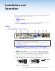
XTP T HDMI Rear Panel Connectors
POWER
12V
HDMI
1.0 A MAX
Rx GTx
RS-232 IR
RxTx
−+−+
LR
LOOP-THRU
RESET
AUDIO
OFF
ON
AUDIO
SIG LINK
XTP OUT
INPUTS
OVER XTP
LAN
abcd efg
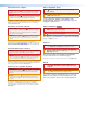
Figure 2. XTP T HDMI Rear Panel Connectors
NOTES:
• For HDMI cables, the maximum cable length is 15 feet.
• Use Extron LockIt lacing brackets to secure HDMI connectors to the device (see
HDMI LockIt on page 8).
• Video input from a DisplayPort source must be a dual mode DisplayPort source.
a
HDMI input connector — Connect a digital video source to the female HDMI
connector. It can accept HDMI, DVI (with an appropriate adaptor), or DisplayPort video
signals.
b
HDMI Loop-thru connector — Connect a digital video display to the female HDMI
Loop-thru connector to locally display the input source (see HDMI Audio Switch on
page 14 to select local audio output options). Displays that are not HDCP compliant
display a green screen when HDCP encrypted content is sent to them.
c
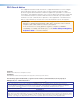
Analog audio inputs — Connect a balanced or unbalanced analog audio source to
the 5-pole captive screw connector for stereo analog audio input.
Unbalanced Audio Input
Balanced Audio Input
Tip
Ring
Tip
Ring
Slee
ves
Tip
Sleeve
Sleeve
Tip
LR
LR
Do not tin the wires!
Figure 3. Audio Input Wiring
4XTP T HDMI Transmitter and XTP R HDMI Receiver • Installation