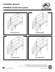
Installation Manual FORTRESS® OSHA Stair System 3-Tread at 25.5” 3-Tread at 34” 4-Tread at 34” 4-Tread at 42.5” 3-YEAR WARRANTY. Please register at www.ezaccess.com/warranty-satisfaction. © EZ-ACCESS®, a division of Homecare Products, Inc. All rights reserved. All text and images contained in this document are proprietary and may not be shared, modified, distributed, reproduced, or reused without the express written permission of EZ-ACCESS.
INTRODUCTION Throughout this manual, the term “system” refers to the entire FORTRESS® OSHA Stair System, including its components, hardware, and any/all optional equipment. SYMBOLS The WARNING symbol indicates a potentially hazardous condition/situation. The safety warnings throughout this manual, and on your equipment, if any, are for the protection of people and property.
WARNINGS, CONT’D. Aluminum conducts electricity. Do not use the system during electrical storms or in proximity to damaged or exposed wiring. Properly support and restrain the system in transit or storage. For additional care, usage, or general safety information, please call 1-800-451-1903.
BASIC SYSTEM COMPONENTS FORTRESS OSHA Stair System Component Descriptions Diagram Letter (FIG.
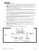
1. INSTALLATION 1.1. Set the platform on its side. 1.2. Loosen platform leg adjustment bolts in each platform corner pocket, but do not remove them. Adjust legs to the desired height and securely retighten platform leg adjustment bolts and washers (FIG. 2). If using oversized feet, see ‘OVERSIZED FEET INSTALLATION (OPTIONAL EQUIPMENT)’ section. 1.3. Set the platform in an upright position. 1.4. Readjust the height of each platform leg as necessary to level the platform.
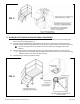
FIG. 3 2. OVERSIZED FEET INSTALLATION (OPTIONAL EQUIPMENT) 2.1 Loosen the leg adjustment bolts in each platform and riser corner pocket, but do not remove them; then remove the existing legs (FIG. 2). 2.2 Insert the legs included with the oversized feet into the corner pockets with the open side of the channel oriented toward the leg adjustment bolt and washer and the square nut inside the leg (FIG. 4). The two short legs install in the bottom of the riser and the four long legs install in the platform. 2.
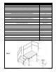
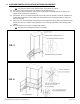
3. PLATFORM CANOPY INSTALLATION (OPTIONAL EQUIPMENT) 3.1 Remove handrails from the system (if installed) and set aside. Use extreme caution on the platform when no handrails are present. 3.2 Insert 1-1/2” square canopy posts into platform corner pockets (FIG. 5). 3.3 Set canopy roof on canopy posts. Insert top of canopy posts into canopy roof corner pockets and tighten corner pocket set screws (FIG. 5). 3.
4. MAINTENANCE AND SAFETY 4.1. Always exercise caution when handling, assembling, and or using the system. Proper maintenance and upkeep of the system surface is vital. 4.2. Regular inspection of the system is required to identify worn, loose, or damaged parts, which must be immediately repaired by your original installer or a qualified technician. Failure to do so may result in serious injury. 4.3.
Thank you for choosing EZ-ACCESS® for your accessibility needs. www.ezaccess.