
Use & Care Guide

Version 06/14 - Page 8
USE AND CARE INFORMATION
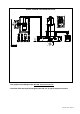
Rangehood Control Panel
All controls are located on the right side of the rangehood.
Light On/Off Switch
TheOn/Off switch for the halogen light is located behind the
front trim. Moving the switch to the 1 Position turns the light
On. Moving the switch to the 0 position turns the light off.
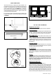
Blower Speed Switch
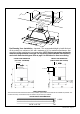
B in FIGURE 10 shows the speed control switch for the
blower. Moving the switch to the 1 Position turns the blower
on LOW. Moving the switch to the 2 Position turns the blower
on MEDIUM. Moving the switch to the 3 Position turns the
blower on HIGH. Moving the switch to the 0 Position turns
the blower off.
Automatic Operation
As long as the blower and light switches are on, the blower
and light will automatically operate when the visor is opened
and shut off when the visor is closed.
For Best Results
Start the rangehood several minutes before cooking to develop
proper airow. Allow the unit to operate for several minutes
after cooking is complete to clear all smoke and odors from
the kitchen.
Cleaning
The metal grease lters should be cleaned frequently in hot
detergent solution or placed in the dishwasher. Clean exterior
surfaces with hot soapy water. Using abrasives and scouring
agents can scratch rangehood nishes and should not be
used to clean nished surfaces.
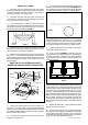
Replacing the halogen lamp
CAUTION the bulb MAY BE HOT
To replace the halogen bulb, see (Figure 11)
Before attempting to replace the lamp, make sure the light
switch is off, the bulb CAUTION may be hot. Remove the
cover snap-on lamp levering under the metal ring, supporting
it with one hand. Remove the halogen lamp from the lamp
holder by pulling gently. Replace the lamp with a new one of
the same type, making sure that you insert the two pins into
the slots on the lamp holder. Replace the cover snap-on lamp.
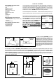
FIGURE 10
FRONT TRIM OPTIONS
The Cristal comes with a stainless front strip installed. Op-
tional black and white strips are available as accessories for
purchase. To change the front strip, remove the three phillips
screws located behind the strip (FIGURE 8). If necessary,
the front strip can be adjusted by loosening the three phillips
screws and sliding the strip up or down. Tighten screws when
you have the strip properly placed.
For a custom front strip, a local cabinet shop can make a strip
to match your cabinets. The front strip dimensions are given
in FIGURE 9.
FIGURE 8
1 15/32"
FIGURE 9
3/4"
29 7/8" or 35 7/8"
Visor
Front
Strip
Three Screws
B
2x
FIGURE 11