INCA PRO PLUS Installation Instructions Use and Care Information Instructions d'installation Utilisez et d'entretien INPL3019SSNB-B INPL3619SSNB-B INPL3622SSNB-B INPL4219SSNB-B INPL4819SSNB-B INPL4822SSNB-B
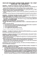
READ AND SAVE THESE INSTRUCTIONS BEFORE YOU START INSTALLING THIS RANGEHOOD WARNING: - TO REDUCE THE RISK OF A RANGE TOP GREASE FIRE: a) Never leave surface units unattended at high settings. Boilovers cause smoking and greasy spillovers that may ignite. Heat oils slowly on low or medium setting. b) Always turn hood ON when cooking at high heat or when flambeing food (i.e. Crepes Suzette, Cherries Jubilee, Peppercorn Beef Flambé). c) Clean ventilating fans frequently.
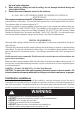
. 4. the local code authorities. When cutting or drilling into wall or ceiling, do not damage electrical wiring and other hidden utilities. Ducted fans must always be vented to the outdoors. ALL WALL AND FLOOR OPENINGS WHERE THE RANGEHOOD IS INSTALLED MUST BE SEALED. This rangehood requires at least 24" of clearance between the bottom of the rangehood and the cooking surface or countertop. This hood has been approved by UL at this distance from the cooktop. The maximum depth of overhead cabinets is 13".
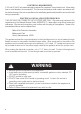
ELECTRICAL REQUIREMENTS A 120 volt, 60 Hz AC-only electrical supply is required on a separate 15 amp fused circuit. A time-delay fuse or circuit breaker is recommended. The fuse must be sized per local codes in accordance with the electrical rating of this unit as specified on the serial/rating plate located inside the unit near the field wiring compartment. ELECTRICAL INSTALLATION WITH WIRING BOX THIS UNIT MUST BE CONNECTED WITH COPPER WIRE ONLY.
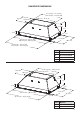
RANGEHOOD DIMENSIONS 21-1/4" (A1) - 22-1/2" (A2) 28-9/16" (A3) - 34-9/16" (A4) 12-5/16" 10-13/16" 18-11/16" 7-15/16" 11" 3-1/8" 1/2" 19-11/16" 28-1/2" (A1) - 34-1/2" (A2) 40-9/16" (A3) - 46-9/16" (A4) 29-1/2" (A1) - 35-1/2" (A2) 41-9/16" (A3) - 47-9/16" (A4) Index A1 A2 A3 A4 15-5/16" 20-11/16" 1/2" Model # INPL3019SSNB-B INPL3619SSNB-B INPL4219SSNB-B INPL4819SSNB-B 22-1/2" (A1) - 34-9/16" (A2) 10-13/16" 18-11/16" 7-15/16" 11" 3-1/8" 1/2" 22-11/16" 34-1/2" (A1) - 46-9/16" (A2) 35-1/2" (A1)
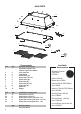
MAIN PARTS 1 9c 9c 10 5 4 5 4 8 9d 6 7 9e Components Ref. Qty. 1 1 4 2 5 2 6 2 6 3 6 4 7 4 7 6 7 8 8 1 10 10 Product Components Hood Body, complete with: Controls, Light, Filters, Blower. Front / back trim Left/right trim Grease filters (30") Grease filters (36"- 42") Grease filters (48") Filter knobs (30") Filter knobs (36"- 42") Filter knobs (48") Grease rail Stopper Ref. 9c 9d 9e 9e 9e Qty.
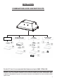
INSTALLATION COMBINATIONS HOOD AND MOTOR KITS INSTALLATION COMBINATIONS HOOD AND MOTOR KITS INLBKIT CAUTION - To reduce risk of fire and electric shock, install this rangehood only with: Remote blower manufacturer by Faber models RB900 and RB1200 or Integral blower manufactured by Faber models IB300 or IB600 or IB1200 or with INLBKIT and generic in-line blower rated max 4.
RECIRCULATING INSTALLATIONS IT IS HIGHLY RECOMMENDED THAT PROFESSIONAL STYLE COOKING ALWAYS BE VENTED TO THE OUTSIDE. For recirculating installations (Figure 1), Charcoal Filters are necessary. Remove all grease filters and set aside. Attach one charcoal filter to each end of the blower. Each charcoal filter attaches to the grid on the side of the RECIRCULATING blower. RotateINSTALLATIONS the filter clockwise to install and counterclockwise to remove (Figure 1A). Replace all grease filters.
3. Install the motor kit into the back of the hood using the 2 screws supplied with the motor kit (Figure 4). 5. Connect the ductwork to the damper and seal all connections with duct tape. 6. Before installing the hood, put the damper A (which is located inside of Kit Internal 300 cfm Blower sku #; IB300 or Internal 600 cfm PRO Blower sku #; IB600) (Figure 6). A FIGURE 4 FIGURE 6 4.
INSTALLATION WITH IB1200 INTERNAL BLOWER (1200 cfm) INSTALLATION WITH IB1200 INTERNAL BLOWER (1200 cfm) 1. Install the Duct Plate B (Figure 7) which came INSTALLATION IB1200 INTERNAL BLOWER with theWITH internal blower onwith toptheof(1200 the cfm) rangehood 1. Install the Plate B (FIGURE 14) whichkit, came internal blower with kit, on top of the rangehood with thecloser holes located closerfront. to the holes located to the Use 9 1.the Install the Plate B (FIGURE 14) which came with the internal front.
INSTALLATION WITH REMOTE BLOWER (RB900 / RB1200) OR IN-LINE BLOWER (INLBKIT) NOTE: FOLLOW THE INSTRUCTIONS INCLUDED WITH THE REMOTE BLOWER TO INSTALL THE/ RB1200) BLOWER ON THE OUTSIDE OF YOUR HOME. INSTALLATION WITH REMOTE BLOWER (RB900 OR IN-LINE BLOWER (INLBKIT) NOTE: FOLLOW THE INSTRUCTIONS INCLUDED WITH THE 1. Install the Plate B with the second wiring box REMOTE BLOWER TO INSTALL THE BLOWER ON THE which came with the remote blower kit, OUTSIDE(Figure OF YOUR13) HOME. on top of the rangehood.
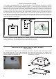
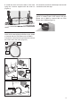
Installation Instructions 1 Cut out the opening in the underside of the cabinet as shown in Figure 1. Y Min.13/16" X Min. 3/4" Outside Hood Dimension 30" x 19" 36" x 19" 36" x 22" 42" x 19" 48" x 19" 48" x 22" Model # X Y INPL3019SSNB-B INPL3619SSNB-B INPL3622SSNB-B INPL4219SSNB-B INPL4819SSNB-B INPL4822SSNB-B 28-5/8" 34-3/4" 34-3/4" 40-3/4" 46-3/4" 46-3/4" 19-7/8" 19-7/8" 22-7/8" 19-7/8" 19-7/8" 22-7/8" 2 Two people may be required for installation. Min. 24" Min.
3 10 9d Fix the hood with 6 screws (9d). Place the 6 stoppers (10) after fixing the hood. 4 Installation of wiring connection Remove the wiring electrical knockout using a flat-blade screwdriver. Feed the Power Supply Cable through the electrical knockout. Connect the Power Supply Cable to the rangehood. Attach the White lead of the power supply (A) to the White lead of the rangehood (D) with a twist-on type wire connector.
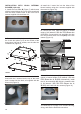
5 For Non-Ducted Recirculation Option Attach each charcoal filter to the black grid on each side of the blower. Press the charcoal filter tightly to the black grid on the 1 blower side 2 and rotate the filter clockwise (towards the front of the insert hood) until it locks into place. Turn counterclockwise (towards the back of the insert hood) to remove.
9a. screws, 4 screws total. lamp. Press and twist the lamp to remove. Then remove the lamp and replace with a new lamp. Rangehood Control Panel The control panel is located in the center of the hood bottom. 9a 9a 3 A 2 Install the grease rail into the back of the hood, into the slots on the inside floor of the rear of the hood. The Grease filters should be installed before operating the rangehood.
FABER CONSUMER WARRANTY & SERVICE All Faber products are warranted against any defect in materials or workmanship for the original purchaser for a period of 1 year from the date of original purchase (requires proof of purchase). This warranty covers labor and replacement parts. Faber, at its option, may repair or replace the product or components necessary to restore the product to good working condition.
VEUILLEZ LIRE ET CONSERVER LA PRÉSENTE NOTICE AVANT DE COMMENCER L'INSTALLATION DE LA HOTTE DE CUISINE AVERTISSEMENT:-POUR RÉDUIRE LE RISQUE D'UN FEU DE GRAISSE SUR LA TABLE DE CUISSON : a) Ne laissez jamais sans surveillance les éléments de la surface de cuisson à température élevée. Les bouillonnements excessifs peuvent provoquer de la fumée et les débordements de graisse peuvent s'enflammer. L'huile doit être chauffée lentement, à une température basse ou moyenne.
2. 3. 4. construction à l'épreuve du feu. Afin de garantir une combustion et une évacuation adéquates des gaz par les conduites de la cheminée des appareils à combustion, une bonne aération est nécessaire pour éviter le refoulement.
! AVERTISSEMENT • Le système de ventilation DOIT déboucher à l'extérieur. • NE FAITES PAS déboucher les conduits dans un grenier ou un autre endroit fermé. • N'UTILISEZ PAS un clapet de sécheuse mural de 4 po. • Il n'est pas recommandé d'utiliser des conduits flexibles. • N'ENTRAVEZ PAS le flux de l'air de combustion et de ventilation. • Le non-respect des exigences en matière de ventilation pourrait entraîner un incendie.
DIMENSIONS DE LA HOTTE 21-1/4" (A1) - 22-1/2" (A2) 28-9/16" (A3) - 34-9/16" (A4) 12-5/16" 10-13/16" 18-11/16" 7-15/16" 11" 3-1/8" 1/2" 19-11/16" 28-1/2" (A1) - 34-1/2" (A2) 40-9/16" (A3) - 46-9/16" (A4) 29-1/2" (A1) - 35-1/2" (A2) 41-9/16" (A3) - 47-9/16" (A4) Légende A1 A2 A3 A4 15-5/16" 20-11/16" 1/2" Modèle # INPL3019SSNB-B INPL3619SSNB-B INPL4219SSNB-B INPL4819SSNB-B 22-1/2" (A1) - 34-9/16" (A2) 10-13/16" 18-11/16" 7-15/16" 11" 3-1/8" 1/2" 22-11/16" 34-1/2" (A1) - 46-9/16" (A2) 35-1/2"
PIÈCES PRINCIPALES 1 9c 9c 10 5 4 5 4 8 9d 6 7 9e Composants Réf. Qté 1 1 4 2 5 2 6 2 6 3 6 4 7 4 7 6 7 8 8 1 10 10 Product Components Bâti de la hotte avec : Commandes, Éclairage, Filtres, Ventilateur. Garniture avant/arrière Garniture gauche/droite Filtres à graisse (30") Filtres à graisse (36"- 42") Filtres à graisse (48") Boutons des filtres (30") Boutons des filtres (36"- 42") Boutons des filtres (48") Gouttière Obturateur Réf.
INSTALLATION COMBINAISONS CAPOT ET KITS DE MOTEUR INSTALLATION COMBINATIONS HOOD AND MOTOR KITS INLBKIT CAUTION - To reduce risk of fire and electric shock, install this rangehood only with: Remote blower manufacturer by Faber models RB900 and RB1200 or Integral blower manufactured by Faber models IB300 or IB600 or IB1200 or with INLBKIT and generic in-line blower rated max 4.
INSTALLATIONS AVEC RECIRCULATION LA VENTILATION ASSOCIÉE À UNE CUISINE DE TYPE PROFESSIONNEL DEVRAIT TOUJOURS ÊTRE ÉVACUÉE À L’EXTÉRIEUR. Pour les installations avec recirculation (Figure 1), il est nécessaire d'installer des filtres à charbon. Retirez tous les filtres à graisse et mettez-les à part. Posez un filtre à charbon à chaque extrémité du ventilateur. Chaque filtre à charbon se fixe à une grille sur le côté du ventilateur.
3. Installez la trousse du moteur dans la hotte en utilisant les 2 vis fournies avec la trousse dans l’arrière de la hotte (Figure 4). 5. Raccordez le conduit au registre et scellez toutes les connexions à l'aide de ruban. 6. Avant d’installer la hotte, posez le registre A (qui se trouve à l’intérieur de la trousse du ventilateur interne 300 PCM, n° d'article IB300 ou du ventilateur interne 600 PCM PRO, n° d'article IB600) (Figure 6). A FIGURE 4 4.
INSTALLATION AVEC LE VENTILATEUR IB1200 INTERNE (cfm 1200) 1. Installez la plaque de canalisation B (Figure 7) INSTALLATION WITH IB1200 INTERNAL BLOWER (1200 cfm) INSTALLATION INTERNAL (1200 cfm) fournieWITH dansIB1200 la trousse duBLOWER ventilateur, sur le haut 1. Install thelaPlate B (FIGURE which came àwith the internal de l’avant. hotte, avec 14) les orifices proximité 1.
INSTALLATION AVEC LE VENTILATEUR À DISTANCE (RB900 / RB1200 OU VENTILATEUR INTÉGRÉ (INLBKIT) NOTE : SUIVEZ LES INSTRUCTIONS INCLUSES AVEC LE VENTILATEUR À DISTANCE INSTALLATION WITH REMOTE BLOWER (RB900 / RB1200) POUR INSTALLER OR IN-LINE BLOWER (INLBKIT) LE VENTILATEUR SUR L'EXTÉRIEUR DE VOTRE MAISON. 1.
Notice d'installation 1 Pratiquez l'ouverture sur la face inférieure de l'armoire, comme illustré à la Figure 1. Y Min.13/16" X Min. 3/4" Dimension extérieure de hotte 30" x 19" 36" x 19" 36" x 22" 42" x 19" 48" x 19" 48" x 22" Modèle # X Y INPL3019SSNB-B INPL3619SSNB-B INPL3622SSNB-B INPL4219SSNB-B INPL4819SSNB-B INPL4822SSNB-B 28-5/8" 34-3/4" 34-3/4" 40-3/4" 46-3/4" 46-3/4" 19-7/8" 19-7/8" 22-7/8" 19-7/8" 19-7/8" 22-7/8" 2 Deux personnes pourraient être requises pour l’installation. Min.
3 10 9d Fixez la hotte en utilisant les 6 vis (9d). Posez les 6 obturateurs (10) après avoir fixé la hotte. 4 Réalisation des branchements Défoncez l'entrée électrique à l'aide d'un tournevis plat. Faites passer le câble d'alimentation dans l'entrée électrique défoncée. Branchez le câble d'alimentation à la hotte. Branchez le fil blanc de l'alimentation (A) au fil blanc de la hotte (D) à l'aide d'un connecteur verrouillé par rotation.
5 Pour option non canalisée avec recirculation d'air Fixez les filtres à charbon à la grille noire de chaque côté du ventilateur. Pressez fermement le filtre à 1 charbon 2 contre la grille noire de chaque côté du ventilateur et faites tourner le filtre dans le sens des aiguilles d'une montre (vers l'avant de la hotte encastrable) jusqu'à ce qu'il soit verrouillé en place. Faites tourner dans le sens contraire des aiguilles d'une montre (vers l'arrière de la hotte encastrable) pour l'enlever.
line the inside hood wall with stainless, 2 and 3 in FIGURE 26 with 9a. screws, 4 screws total. burn extremely hot and serious injury could result from touching a hot lamp. Press and twist the lamp to remove. Then remove the lamp and replace with a new lamp. Panneau de commande de Rangehood Le panneau de commande est plac au centre du fond de capot. 3 A 2 Installez le rail de graisse sur le dos du capot, sur les fentes sur le plancher intérieur de l'arrière du capot.
GARANTIE LIMITÉE ET SERVICE FABER Tous les produits Faber font l'objet d'une garantie contre les défauts de matériel et de maind'œuvre,accordée à l'acheteur original pour une période d'un (1) an à compter de la date d'achat initiale (preuve d'achat requise). Cette garantie couvre les frais de main-d'œuvre et les pièces de rechange. À sa discrétion, Faber peut réparer ou remplacer le produit ou les composants nécessaires à remettre le produit en bon état de marche.
991.0463.