
Installation Manual

8
1. Install the Plate B (Figure 2) which came with
the internal blower kit, on top of the rangehood
with the hole closer to the back of the hood. Use 9
screws supplied with the blower kit.
5
5
4
4
9c
Version 07/11 - Page 8
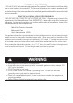
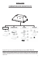
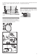
INSTALLATION WITH IB300 / IB600 INTERNAL BLOWER (300
, 600 cfm)
1. Install the Plate B (FIGURE 8) which came with the internal
blower kit, on top of the rangehood with the hole closer to the back
of the hood. Use 9 screws supplied with the blower kit
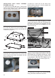
6. (see FIGURE 13) Remove the cover from the field wiring
compartment with a phillips screwdriver. Feed the Power Supply
Cable through the electrical knockout. Connect the Power Supply
Cable to the rangehood cable. Attach the White lead of the power
supply to the White lead of the rangehood with a twist-on type wire
connector. Attach the Black lead of the power supply to the Black
lead of the rangehood with a twist-on type wire connector. Attach
the Power Supply Cable grounding lead to the green screw provided.
Replace the cover.
7. Connect the ductwork to the damper and seal all connections with
duct tape. Install the grease filters and grease rail. (see page 11 for
instructions)
8. Turn the power supply on. Turn on the blower and light. If the
rangehood does not operate, check that the circuit breaker is not
tripped or the house fuse blown. If the unit still does not operate,
disconnect the power supply and check that the wiring connections
have been made properly.
9. CONTINUE TO PAGE 11
FIGURE 8
2. Remove the white plastic covering and install the 4 side trim
pieces to the outside of the hood using (16) part 9b screws, see
the side rail installation in (FIGURE 9).
FIGURE 9
5. Attach the hood to the cabinet using (12) 9c. screws to the
cabinet. FIGURE 12
FIGURE 12
FIGURE 10
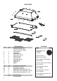
3. Install the motor kit into the hood using the 2 screws supplied
with the motor kit into the back of the hood. (FIGURE 10)
4. Connect the wire that comes with the motor kit from the side
of the motor to the connection on the inside of the light panel in
the hood. The 9 hole end of the wire is installed in the motor, the
6 hole end is connected to the light panel (FIGURE 11)
FIGURE 11
FIGURE 13
B
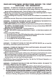
FOR ALL INSTALLATIONS REMOVE ALL WHITE PLASTIC PROTECTIVE COVERING FROM
HOOD, SIDE RAILS, TRIM, GREASE RAILS AND GREASE FILTERS.
2. Remove the white plastic covering and install
the 4 side trim pieces (4-5) to the outside of the
hood using (14) part 9c screws, see the side trim
installation in (Figure 3).
INSTALLATION WITH IB300 / IB600 INTERNAL BLOWER
(300, 600 cfm)
FIGURE 2
FIGURE 3
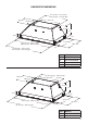
RECIRCULATING INSTALLATIONS
IT IS HIGHLY RECOMMENDED THAT PROFESSIONAL STYLE COOKING ALWAYS BE VENTED
TO THE OUTSIDE. For recirculating installations (Figure 1), Charcoal Filters are necessary. Remove
all grease lters and set aside. Attach one charcoal lter to each end of the blower. Each charcoal lter
attaches to the grid on the side of the blower. Rotate the lter clockwise to install and counterclockwise
to remove (Figure 1A). Replace all grease lters. Recirculating installations also require some duct work
to divert the air out of the top or face or side of the cabinet or custom hood or out of the side / face of
the soft and back into the kitchen. Install at least 15" of vertical run of metal duct (Figure 1) at the air
outlet. Run the duct vertically and secure it at the relevant opening previously cut out at the top or side
of the cabinet or soft. A metal duct cover grille is also recommended. The duct work must not terminate
inside the cabinet or custom hood.
Version 07/11 - Page 7
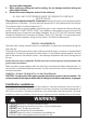
PLAN YOUR DUCTWORK
To ensure that the blower performs to its highest
possible capacity, ductwork should be as short
and straight as possilbe.
The ductrun should not exceed 35 equivalent
feet if ducted using the required minimum of 6"
round duct. For 10" round ducting with the 1200
cfm internal motor or 900 / 1200 remote blower,
use 55 equivalent feet. Calculate the length of
the ductwork by adding the equivalent feet in
FIGURE 5 for each piece of duct in the system
An example is given in FIGURE 6.
For best results, use no more than three 90°
elbows. Make sure that there is a minimum of
24" of straight duct between elbows if more
than one is used. Do not install two elbows
together. If you must elbow right away, do it
as far away from the hood's exhaust opening
as possible.
9 Feet Straight Duct
2 - 90˚ Elbows
Wall Cap
Total System
9.0 feet
10.0 feet
0.0 feet
19.0 feet
FIGURE 6
3.0 feet
5.0 feet
12.0 feet
0.0 feet
45˚ Elbow
90˚ Elbow
90˚ Flat Elbow
Wall Cap
FIGURE 5
FIGURE 4
RECIRCULATING INSTALLATIONS
IT IS HIGHLY RECOMMENDED THAT PROFESSIONAL STYLE COOKING ALWAYS BE VENTED TO THE OUTSIDE. For recirculating
installations (FIGURE 4), Charcoal Filters are necessary. Remove all grease filters and set aside. Attach one charcoal filter to each end
of the blower. Each charcoal filter attaches to the grid on the side of the blower. Rotate the filter clockwise to install and counterclockwise
to remove (FIGURE 4A). Replace all grease filters. Recirculating installations also require some duct work to divert the air out of the top or
face or side of the cabinet or custom hood or out of the side / face of the soffit and back into the kitchen. Install at least 15" of vertical run of
metal duct (FIGURE 4) at the air outlet. Run the duct vertically and secure it at the relevant opening previously cut out at the top or side of
the cabinet or soffit. A metal duct cover grille is also recommended. The duct work must not terminate inside the cabinet or custom hood.
cabinet
or
custom
hood
ceiling
duct
work
duct
work
ceiling
inca pro plus
cabinet
or
custom
hood
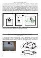
MAKE YOUR CUT-OUTS
1. Disconnect and move freestanding range from cabinet opening to provide easier access
to upper cabinet or custom hood. Put a thick, protective covering over cooktop, set-in range
or countertop to protect from damage or dirt.
2. Determine and make all necessary cuts in the wall and/or ceiling for the ductwork. Install
the ductwork before the rangehood.
3. Determine the proper location for the Power Supply Cable. Use a 1
1/4"
Drill Bit to make
this hole. Install the cable. Use caulking to seal around the hole. DO NOT turn on the
power until installation is complete.
4. Choose the knock out hole to remove for installing the power cable. Use a screwdriver
to snap off the knock out covering. (FIGURE 7 shows inside the wiring box and outside)
FIGURE 4A
inca pro plus
FIGURE 7
FOR ALL INSTALLATIONS
REMOVE ALL WHITE PLASTIC PROTECTIVE COVERING FROM HOOD, SIDE RAILS,
TRIM, GREASE RAILS AND GREASE FILTERS
FIGURE 1
FIGURE 1A