
Product Manual


Mounting Height
When the air flow of the heater is directed vertically, the
minimum mounting height is 6 feet (1829 mm), the maximum
mounting height is 11 feet (3353 mm). When the air flow of the
heater is directed horizontally the minimum mounting height is 6
feet (1829 mm) and the maximum recommended height is 8 feet
(2438 mm).
Distance from Walls
When the heater is mounted so that the air flow direction is at
an angle from horizontal to 45° downward, the distance from the
mounting bracket to any wall should be at least 13 inches (330.2
mm). When the heater is mounted so that the direction of air
flow is at an angle between 45° downward and vertical, the dis-
tance from the mounting bracket to any wall should be at least
48 inches (1219 mm).
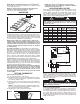
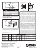
1. Mounting the Bracket
Locate a stud in the ceiling and attach the mounting bracket to
the ceiling joist as shown in figures 3-A or 3-B. You will need to
remove the mounting bracket from the heating unit by loosening
the bracket screws with a wrench and slipping the handle off
over the screw heads. Remember to place a washer on the
screws before you insert them through the holes in the mount-
ing bracket and screw them into the stud. Tighten the screws
enough to securely hold the heating unit with the air flow point-
ed in the proper direction.
2. Hanging the Heater
Attach the heating unit to the mounting bracket. Lift the heater
up and into the mounting bracket. The bracket screws, located
on each side of the heating unit, allow the heater to be attached
easily to the mounting bracket by aligning the screws with the
keyhole slots in the mounting brackets. If the heater is to be tilt-
ed, it must be positioned in the lower keyhole slots (see Fig. 4).
Tighten the bracket screws with a wrench so the unit is secure-
ly suspended at the desired horizontal or vertical level.
3. Connecting the Power
To connect the power to the heater, simply remove the screw
from the front of the unit. This allows the hinged bottom to open,
providing access to the electrical wiring and connectors. (See
Fig. 4)
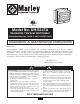
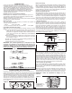
Attach the cable connectors to the unit (See Fig. 1) and slide the
10 gauge wire through the cable connector. Pull enough of the
wire through the connector so you will have enough wire to work
with when you make the the connections.
INTRODUCTION
Your new heater has unmatched operating flexibility, designed
to meet a variety of heating requirements by simply switching
a few easily accessible wires located in the base of the unit.
With heat output ranging from 6,396 to 17,065 BTU per hour,
this unique feature lets you use a single unit to meet a wide
range of heating applications.
This manual shows you how to install, operate, and maintain
your UH-524TA electric heater.
Unpacking Your New Heater
Remove the heater from the box and inspect it for any damage.
If it appears to be damaged, immediately return it to the store
from which you purchased it.
Check the contents of the box to make sure it contains one
heating unit and one mounting bracket.
Tools Needed
You will need the following tools to install your UH-524TA
electric heater:
• Screwdriver • Needle nose pliers • Pliers
• Electric Drill and 1/4" (6.35) bit •Adjustable wrench
Hardware Needed
You will also need the following hardware for installation:
• Enough 10 ga. min. insulated copper conductor (with
ground) wire to run power from the breaker/ fuse to the
heater. Only use copper wire rated at least 75° C. Do not
use aluminum wire with this unit.
• Proper size fuses and circuit breakers in accor-dance
with the National Electrical Code. Also see Table 1, page
5.
• Screw wood, 3/8" x 2" (9.5 mm x 50 mm) Lag bolts (Qty.
1 or 2).
• Washer, 3/8" (9.7 mm) (Qty. 2)
• Wire connectors sized to your application.
NOTE: For certain applications, conduit may be required
(see Fig. 1). Check local electrical codes. Also, if you run
the wiring in conduit and wish to be able to turn the heater,
be sure to purchase enough flexible conduit to allow the
heater to be turned.
FINDING THE BEST LOCATION
FOR YOUR HEATER
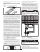
The heater should be installed out of traffic areas and at least 6'
off the floor. The direction of air flow should not be restricted (ie:
by columns or machinery) and the air flow should wipe exposed
walls, rather than blowing directly at them. When more than one
heater is used in an area, the heaters should be arranged so
that the air discharge of each heater supports the air flow of the
others to provide best circulation of warm air, as indicated in fig-
ure 2, below.
Figure 1
CEILING JOIST
WASHER
3
/8" DIAGONAL
LAG BOLT
BRACKET
C
EILING JOIST
WASHER
3
/8" DIAGONAL
LAG BOLT
BRACKET
Figure 3-A
Figure 3-B
Single-Screw Mounting
Double-Screw Mounting
2
Figure 2
Conduit
Conduit
Connector
Flexible Conduit
Flexible Conduit Connector
Flexible NM Cable
Flexible NM Cable Connector
Connectors, cable, and hardware used to wire the UH-524TA
Figure 4
REMOVE SCREW TO OPEN DOOR
USE BOTTOM KEYHOLE
SLOTS IF HEATER IS
TO BE TILTED DOWN