
Product Manual


NOTE: Wiring compartment volume = 370 in
3
(6063 cm
3
)
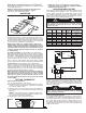
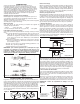
Connect the wire to the power terminal block located in the base
of the heater (See Fig. 5).
NOTE: To decrease the heat output of the heating unit,
see Table 1 and schematic diagram on page 4.
Turn on the power at the main service.
OPERATION
Setting the Thermostat
Rotate thermostat knob clockwise to high position. After room
reaches desired comfort level, rotate thermostat knob counter-
clockwise until the thermostat clicks off. (Note that the fan delay
will keep the fan running until the elements cool.) Heater will
cycle on and off to maintain room temperature.
NOTE: The first time you operate the unit, it may smoke
slightly. This is due to the residual cleaning agents used to
clean the element when the heater is manufactured. This is
normal and does not indicate a problem with the unit. This
condition will stop after the heater has been in operation
for a few minutes.
Automatic Fan Delay: The UH-524TA has an automatic fan
delay. When the thermostat calls for heat, fan action is delayed
momentarily until the heating elements warm. This prevents the
circulation of cold air. When the heater raises the temperature of
the room to the thermostat set point, the heating element is
turned off but the fan will continue to run until the heating ele-
ment cools down. This prevents exposing the unit to residual
heat, provides a higher comfort level and prolonged element life.
Thermal Cutout: The UH-524TA is also equipped with a
thermal cutout which will automatically shut off the heater in the
event of overheating. The heater will turn on when the operat-
ing temperature returns to normal. Should the unit overheat and
activate the thermal cutout cycle, the cause of the overheating
should be determined before further operation.
NOTE: If the unit is installed in an area where the tempera-
ture is below 50° F, the fan may cycle on and off until the
temperature in the room rises above 50° F, this is normal
and does not indicate a problem with the unit. As soon as
the heater warms the air in the room above 50°, the unit will
cycle normally.
SETTING THERMOSTAT
Adjusting Air Flow Direction
You can adjust the direction of air flow by:
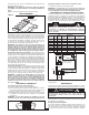
A. Turning the unit. If the unit has been installed with a single
lag bolt, as shown in the Figure 6, simply turn the entire unit
as needed to adjust air flow.
B. Tilting the unit. Loosen the bracket screws, tilt the heater to
the desired position, and re-tighten the bracket screws (see
Figure 4).
NOTE: To tilt the heater it must be mounted in bottom key
hole slots of mounting bracket to maintain adequate clear-
ance and prevent possible overheating.
C. Adjusting the louvers to the desired position.
G
R
E
E
N
(
o
r Ba
r
e
Co
p
p
e
r
)
W
HIT
E
BL
ACK
L1
L2
B
OT
T
OM
V
I
E
W
P
OW
E
R
T
E
RMI
NA
L
B
L
OC
K
Figure 5
3
NOTE: The louvers are designed so they can not be
completely closed. Do not attempt to defeat this feature,
damage to the unit can result.
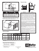
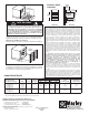
ADJUSTING HEAT OUTPUT
Heat output can be increased or decreased by switching wires
at the wattage change terminal board. The heater is factory
wired to deliver a heat output of 17,065 BTU per hour. Should
your particular application require less heat output, refer to
Table 1 below and change the wires at the wattage change ter-
minal board as shown in Wiring Diagram Fig. 7.
MAINTENANCE
Because of its rugged design, superior engineering, and high-
quality craftsmanship, the UH-524TA requires little mainte-
nance. With proper care, your electric heater should last a life-
time, but seasonal cleaning is recommended to maintain the
efficiency of the heater.
Cleaning the Heating Element
To clean the heating element, loosen (but do not remove) the
four Phillips head screws located behind the louvers in the cor-
ners of the louver housing. (See Fig. 8) Grasp the louver hous-
ing on both sides, lift up, and pull out. This provides access to
the heating element. Remove dust or lint with a soft brush or a
vacuum cleaner. Replace the louver housing and tighten the
Phillips head screws.
Figure 6
TABLE 1. HEAT OUTPUT ADJUSTMENTS
MAX
F
USE HEATER MOVE JUMPERS FROM
BTU/HR VOLTS WATTS SIZE AMPS C-D TO A-B
1
7065 240 5000 30 20.9 NONE
14215 240 4165 25 17.4 BLUE
11365 240 3332 20 13.9 BLUE & YELLOW
8
533 240 2500 15 10.4 BLUE, YELLOW & RED
12799 208 3750 25 18.0 NONE
1
0659 208 3123 20 15.0 BLUE
8533 208 2500 15 12.0 BLUE & YELLOW
6396 208 1874 15 9.0 BLUE, YELLOW & RED
B
LK
1
2
3
4
5
6
E
LEMENT
H
I
L
IMIT
FAN
CONT.
7
8
9
10
11
12
CD AB
WATTAGE CHANGE
TERMINAL BOARD
GROUND
THERMOSTAT
L1 L2
POWER
TERMINAL
BLOCK
FIELD
WIRING
F
AN
M
OTOR
RD
YL
BLU
Figure 7
TO PREVENT POSSIBLE ELECTRIC SHOCK, DISCON-
NECT POWER TO THE HEATER AT THE MAIN SERVICE
BOX BEFORE ATTEMPTING TO ADJUST THE HEAT OUT-
PUT OF THIS UNIT.
WARNING
!
TO PREVENT POSSIBLE ELECTRIC SHOCK, ALL POWER
MUST BE SHUT OFF AT THE MAIN SERVICE BEFORE
INSPECTING OR CLEANING.
WARNING
!