
Use and Care Manual
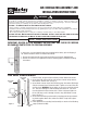

REMOVAL OF FRONT GUARD FOR
CLEANING OR MAINTENANCE
SECONDARY SUPPORT CABLE INSTALLATION
FOR WALL/CEILING AND I-BEAM MOUNTS
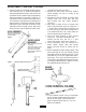
1. Turn off fan and unplug from power source!
2. Insert two screwdrivers as illustrated. (See fig. 14)
3. Carefully apply pressure on edge of rear guard
inward and pressure to front edge of guard outward
to disengage hook.
4. Work around guard until all hooks are disengaged.
5. To re-attach front of guard repeat step 3 of Fan Guard
Assembly instructions.
NOTE: Be careful not to bend edge of guards.
Figure 14
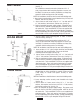
Figure 15
1. Always unplug power cord when servicing fan.
2. To reduce the risk of fire or electric shock do not use this
fan with any solid state motor speed control.
3. Never allow fan to become wet or damp.
4. Never move or adjust fan height while fan is running.
5. Never put fingers or foreign objects through fan guard.
6. Motor is permanently lubricated - do not oil.
7. Check all hardware periodically to make sure all is
secure. Loose hardware could cause damage to fan.
8. A secondary support cable should be used with any
overhead installation.
9. Extension cords should not be used with fans. If it is
necessary to use one, use only three wire extension
cords with three prong grounded type plugs. Refer to
table for correct wire size.
EXTENSION CORD LENGTH WIRE SIZE AWG
UP TO 25 FEET 14
25-50 FEET 12
GENERAL SAFETY INFORMATION
Part No. 5200-2391-003 02/07
ECR 37011
4
Figure 16
Loop secondary support cable around top of fan guard as
indicated. Secure cable making sure both front and back guards are
inside loop, but that cable is not allowed to touch fan blade (See fig.
15). Secure ends with two cable clamps, loop other end of cable
around any permanent sturdy structural member close to fan (I-
beam, rafter, joist, etc...) and secure ends with two cable clamps.
IMPORTANT NOTICE: It is important to note the proper installation
position of the cable clamps as illustrated. To obtain maximum hold-
ing power, install U-bolt section of clip on dead or short end of cable
and saddle on long end of cable(See fig. 16). Improper installation
reduces the efficiency of the connection by as much as 40 percent.
HOW TO OBTAIN WARRANTY SERVICE AND
WARRANTY PARTS PLUS GENERAL INFORMATION
1. Warranty Service or Parts 1-800-642-4328
2. Purchase Replacement Parts 1-800-654-3545
3. General Product Information www.marleymep.com
Note: When obtaining service always have the following:
1. Model number of the product
2. Date of manufacture
3. Part number or description
470 Beauty Spot Rd. East
Bennettsville, SC 29512 USA