
Datasheet

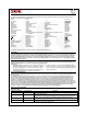

QSB34GR / QSB34ZR / QSB34CGR / QSB34CZR — Surface-Mount Silicon Pin Photodiode
© 2005 Fairchild Semiconductor Corporation www.fairchildsemi.com
QSB34GR / QSB34ZR / QSB34CGR / QSB34CZR Rev. 1.2.0 6
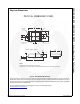
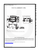
Physical Dimensions (continued)
Figure 8. PLCC DETECTOR (ACTIVE)
Package drawings are provided as a service to customers considering Fairchild components. Drawings may change in any manner
without notice. Please note the revision and/or date on the drawing and contact a Fairchild Semiconductor representative to verify or
obtain the most recent revision. Package specifications do not expand the terms of Fairchild’s worldwide terms and conditions, specifically the
warranty therein, which covers Fairchild products.
Always visit Fairchild Semiconductor’s online packaging area for the most recent package drawings:
http://www.fairchildsemi.com/packaging/
.
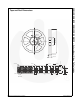
Recommended Solder Screen
Pattern (For Reference Only)
4.50
4.30
0.90
0.70
4.00
3.80
6.70
6.10
1.10
0.90
1.70
1.50
0.20
0.10
0.012 (0.30)
1.20
0.10
0–5°
Anode
Photosensitive
surface
1.50
Package
Center
Chip Center
0.175
Chip
Note:
1. All dimensions in mm
2. Pattern applies to both QSB34GR and QSB34ZR
7.4
4.3
1.55
1.8
Note:
1. Dimensions for all drawings are in mm.
2. Tolerance of ±0.13 on all non-nominal dimensions unless otherwise specified.
PLCC 2L (QSB34ZR / CZR)