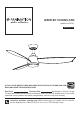
AIREFLEX CEILING FAN ™ MODEL #LP7675** Español p. 21 ATTACH YOUR RECEIPT HERE AND REGISTER YOUR FAN AT FANIMATION.COM READ AND SAVE THESE INSTRUCTIONS Date Code Purchase Date Net Weight 11.25 lbs (5.10 kgs) For best and quickest service please provide date code. You can find the date code on the carton, hand-held remote (inside of the battery compartment), receiver or top of fan housing.
Important Safety Instructions WARNING: To avoid fire, shock and serious personal injury, follow these instructions. 1. Read your owner’s manual and safety information before installing your new fan. Review the accompanying assembly diagrams. 2. Before servicing or cleaning unit, switch power off at service panel and lock service panel disconnecting means to prevent power from being switched on accidentally.
LIMITED LIFETIME WARRANTY Extends to the original purchaser of a Fanimation fan from an authorized Fanimation dealer/retailer only 1. LIMITED LIFETIME MOTOR WARRANTY - If any part of your fan motor fails, due to a defect in materials or workmanship during the lifetime of the original purchaser, Fanimation will provide the replacement part free of charge, when the defective fan is returned to our national service center. Proof of purchase is required.
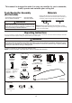
This manual is designed to make it as easy as possible for you to assemble, install, operate and maintain your ceiling fan Materials Tools Needed for Assembly (Not Included) • One Phillips head screwdriver • One ¼˝ blade screwdriver Wiring outlet box and box connectors must be of type required by local code.
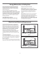
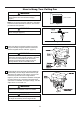
Energy Efficient Use of Ceiling Fans Using the Ceiling Fan Year Round Ceiling fan performance and energy savings rely heavily on the proper installation and use of the ceiling fan. Here are a few tips to ensure efficient product performance. Choosing the Appropriate Mounting Location Ceiling fans should be installed, or mounted, in the middle of the room and at least 7 feet from floor to the blade and 18 inches from wall to the blade.
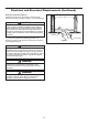
Electrical and Structural Requirements (Continued) Deep box with brace (Figure 3) Paired with a deep box, this hanger is meant to span between two joists and takes the place of wooden blocking. CEILING JOIST WARNING To reduce the risk of fire, electric shock, or personal injury, mount to outlet box marked acceptable for fan support of 15.9 kg (35 lbs) or less and use mounting screws provided with the outlet box.
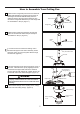
How to Assemble Your Ceiling Fan 1. Remove the hanger ball portion from the downrod/ hanger ball assembly by loosening the set screw in the hanger ball until the ball falls freely down the downrod. Remove the pin from the downrod, then remove the hanger ball. Retain the pin and hanger ball for reinstallation in Step 6. (Figure 1) Pin Downrod Set Screw Hanger Ball Figure 1 2. Remove the hairpin clip and clevis pin from the bottom of the downrod. Retain the pin and clip for reinstallation in Step 4.
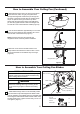
How to Assemble Your Ceiling Fan (Continued) 6. Reinstall the hanger ball on the downrod as follows. Route the brown, blue, red, gray and yellow wires through the hanger ball. Position the pin through the two holes in the downrod and align the hanger ball so the pin is captured in the groove in the top of the hanger ball. Pull the hanger ball up tight against the pin. Securely tighten the set screw in the hanger ball. A loose set screw could create fan wobble. (Figure 6) Figure 6 7.
How to Hang Your Ceiling Fan WARNING To avoid possible fire or shock, be sure electricity is turned off at the main fuse box before hanging. (Figure 1) Main Fuse Box NOTE: If you are not sure if the outlet box is grounded, contact a licensed electrician for advice, as it must be grounded for safe operation. Figure 1 WARNING The fan must be hung with at least 7’ of clearance from floor to ceiling fan. (Figure 2) Figure 2 1.
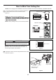
How to Wire Your Ceiling Fan NOTE: If fan or supply wires are different colors than indicated, have this unit installed by a qualified electrician. 1. To set the code on receiver unit, slide dip switches to the same positions as set on the remote control. (Figure 1) Receiver Unit Dip Switch ON NOTE: The remote unit has 32 different code other remote units, simply change the combination code 1 2 3 4 5 NOTE: Factory setting is all up. Do not use this position.
How to Wire Your Ceiling Fan (continued) 3. Connect wires using connectors as shown in Figure 4. WARNING RECEIVER HARDWARE USED: WIRE CONNECTORS Check to see that all connections are tight, including ground, and that no bare wire is visible at the wire connectors. Do not operate fan until the blades are in place. Noise and motor damage could result. L BLACK N WHITE x8 CAUTION: INCORRECT WIRE CONNECTION COULD DAMAGE THIS RECEIVER.
How to Install Your Canopy Housing NOTE: This step is applicable after the neccessary wiring is completed. 1. Assemble canopy by rotating key slot in canopy over shoulder screw in hanger bracket, taking care not to pinch the wires. Tighten shoulder screw. Fully assemble and tighten second shoulder screw that was previously removed.
How to Assemble Your Light Kit 1. Remove one of the three screws in the support bracket at the bottom of the motor assembly. Retain the screw for later and slightly loosen the remaining two screws. (Figure 1) Motor Assembly 2. Assemble the light kit to the support bracket using the two key slots in the light kit. Replace the previously removed screw and securely tighten all three screws. (Figure 2) Figure 1 Motor Assembly Light Kit Figure 2 3. Remove one of the three screws in the light kit.
How to Assemble Your Light Kit (Continued) 6. Secure the glass to light kit by twisting in a clockwise direction. Twist the glass gradually until it snaps on to the light kit. Do not over-tighten. (Figure 6) Light Kit Glass Figure 6 How to Operate Your Ceiling Fan 1. IMPORTANT: Using a full range dimmer switch (not included) to control fan speed will damage the fan. To reduce the risk of fire or electrical shock, do not use a full range dimmer switch to control the fan speed. (Figure 1) 2.
How to Operate Your Ceiling Fan (Continued) 4. To make fan operational, install two 3V batteries (included) in hand-held remote transmitter, with fan power off. Then, follow the remote code setting process. If not used for long periods of time, remove battery to prevent damage to transmitter. Store the remote away from excessive heat or humidly. (Figure 4) 3V CR2032 Battery (2 pcs) WARNING Chemical Burn Hazard. Keep batteries away from children. Figure 4 5.
How to Operate Your Ceiling Fan (Continued) • Home Away: Tap this button, the light will blink twice signaling this feature is on; the fan will turn off and the light will randomly turn on and off while you are away. Pressing any button will cancel the feature. • Fresh Air: Fan speed will modulate to simulate a natural breeze. • Safe Exit: Tap once, the light will blink once; fan and light will turn off after 1 minute. Pressing any button will cancel this feature.
Troubleshooting WARNING For your own safety turn off power at fuse box or circuit breaker before trouble shooting your fan. Trouble Probable Cause Suggested Remedy 1. Fuse or circuit breaker blown. 1. Check main and branch circuit fuses or circuit breakers. 2. Loose power line connections to the fan, or loose switch wire connections in the switch housing. 2. Check line wire connections to fan and switch wire connections in the switch housings. 1.
Parts List Model #LP7675** Ref.
AIREFLEX ™ Model LP7675** Exploded-View Illustration 1 12 2 3 4 5 6 7 12 11 8 10 12 9 NOTE: The illustration shown is not to scale or its actual configuration may vary. Product/parts are subject to change without notice.
10983 Bennett Parkway Zionsville, IN 46077 Phone: 888-567-2055 Outside U.S.: 317-733-4113 FAX: 866-482-5215 FANIMATION.COM 2020/08 V.
VENTILADOR DE TECHO AIREFLEX™ MODELO #LP7675** ADJUNTE SU RECIBO AQUÍ Y REGISTRE SU VENTILADOR EN FANIMATION.COM LEA Y GUARDE ESTAS INSTRUCCIONES Código de fecha Fecha de compra Peso neto 5.10 kgs (11.25 lbs) Para ofrecer un servicio rápido y de calidad, por favor suministre el código de fecha. Puede encontrar el código de fecha en el paquete, en el mando a distancia (dentro del compartimento de las pilas), en el receptor o en la parte superior de la carcasa del ventilador.
Instrucciones de seguridad importantes ADVERTENCIA: Siga estas instrucciones para prevenir incendios, descargas eléctricas y lesiones personales graves. 1. Lea el manual del propietario y la información de seguridad antes de instalar su nuevo ventilador. Observe los diagramas de ensamblaje adjuntos. 2. Antes de llevar a cabo el mantenimiento o la limpieza de la unidad, desconecte la electricidad en el panel de servicio y bloquee los medios de desconexión del mismo para evitar que se active accidentalmente.
GARANTÍA LIMITADA DE POR VIDA Se extiende al comprador original del ventilador Fanimation solo desde un distribuidor/minorista autorizado de Fanimation 1.
Instrucciones para el desempaque Para su comodidad, marque cada uno de los pasos. A medida que completa cada paso, coloque una marca de verificación. Con esto se asegurará de completar todos los pasos y podrá saber desde dónde retomar si fuera interrumpido. ADVERTENCIA No instale ni utilice el ventilador si falta alguna pieza o si hay piezas dañadas. Este producto está diseñado para ser utilizado sólo con las piezas suministradas o los accesorios indicados por Fanimation específicamente para el mismo.
Uso eficiente de la energía en ventiladores de techo El nivel de rendimiento y ahorro de energía de los ventiladores de techo dependen de su correcta instalación y uso. Acontinuación le presentamos algunas sugerencias para asegurar un rendimiento eficiente del producto.
Requisitos eléctricos y estructurales (cont.) Uso del soporte (Figura 3) Conectado a una caja de distribución eléctrica, este colgador sirve para abarcar el espacio entre dos vigas y ocupar el lugar de bloqueo de la madera. Vigas del techo ADVERTENCIA Para reducir el riesgo de incendios, descargas eléctricas o lesiones personales, fije el ventilador a la caja de distribución eléctrica marcada como aceptable para soporte de ventilador de 15,88kg (35lb).
Cómo ensamblar el ventilador de techo 1. Extraiga la pieza de la bola colgante de la unidad de la bola colgante / varilla aflojando el tornillo de presión de la bola colgante hasta que la bola se libere de la varilla. Retire el pasador del barral y luego extraiga la semiesfera. Conserve el pasador y la semiesfera para su reinstalación en el Paso 6. (Figura 1) Pasador Varilla Tornillo de fijación Bola colgante Figura 1 2.
Cómo ensamblar el ventilador de techo (cont.) 6. Vuelva a colocar la semiesfera en el barral como seindica a continuación. Pase los cables de marrón, azul, rojo, gris y amarillo a través de la semiesfera. Pase el pasador a través de los dos orificios en el barral y alinee la semiesfera de modo que el pasador quede atrapado en la ranura de la parte superior de la misma. Empuje la semiesfera hacia arriba, bien ajustada contra el pasador. Ajuste firmemente el tornillo de fijación en la semiesfera.
Cómo colgar el ventilador de techo ADVERTENCIA Para evitar una posible descarga eléctrica, asegúrese de cortar la alimentación eléctrica de la caja de fusibles principal antes de colgar el ventilador. (Figura 1) Principal Caja De Fusibles NOTA: Si no está seguro de si la caja de salida tiene conexión a tierra, pida consejo a un electricista certificado, ya que debe tener conexión a tierra para un funcionamiento seguro.
Cómo realizar la instalación eléctrica del ventilador de techo NOTA: Si los cables de suministro o del ventilador son de colores diferentes que los indicados, contrate a un electricista calificado para que realice la instalación. 1. Para configurar el código de unidad del receptor. Deslice los interruptores de código a las mismas posiciones que en el transmisor. (Figura 1) Unidad del receptor Interruptores ON NOTA: Los ajustes de fábricas vienen con todos los interruptores hacia arriba.
Cómo realizar la instalación eléctrica del ventilador de techo (cont.) 3. Realice las conexiones de cables al bloque del terminal como se muestra en la Figura 4. ADVERTENCIA Verifique que todas las conexiones estén ajustadas, incluida la conexión a tierra, y que no haya conductores desnudos visibles en los conectores. No opere el ventilador hasta que las aspas estén instaladas. Podría ocasionar ruidos y daños al motor. PRECAUCIÓN: UNA CONEXIÓN INCORRECTA DEL CABLE PODRÍA DAÑAR ESTE RECEPTOR.
Cómo instalar la carcasa de la cubierta NOTA: Este paso se debe realizar luego de completar lacompleted. instalación eléctrica necesaria. 1. Instale la cubierta rotando la ranura clave en la cubierta sobre el tornillo de hombro del soporte del gancho, teniendo cuidado de no pillar los cables. Fije el tornillo de hombro. Instale adecuadamente y fije el segundo tornillo de hombro que fue anteriormente guardado.
Cómo ensamblar su el kit de iluminación 1. Extraiga uno de los tres tornillos del soporte ubicado en la parte interior de la unidad del motor. Guárdelos para después y afloje levemente los otros dos tronillos. (Figura 1) Motor Figura 1 2. Instale la ensamble de la placa de iluminación en el soporte utilizando las dos ranuras principales de conexión. Vuelva a colocar el tercer tornillo y asegure los tres tronillos. (Figura 2) Motor Figura 2 Ensamble de la placa de iluminación 3.
Cómo ensamblar su el kit de iluminación (cont.) 6. Asegure el vidrio en la la ensamble de la placa de iluminación girándolo en el sentido de las agujas del reloj. Gire el vidrio gradualmente hasta que encaje en la ensamble de la placa de iluminación. Sin apretar demasiado. (Figura 6) Ensamble de la placa de iluminación Vidrio Figura 6 Cómo utilizar su ventilador de techo 1.
Cómo utilizar su ventilador de techo (cont.) 4. Para que el ventilador sea functional, instale las pila (incluidas) de 3V en el transmisor del mando a distancia. Mientras el ventilador esté apagado. A continuación, siga el proceso de fijación remota de código. Si no se utiliza el ventilador durante un largo periodo de tiempo, extraiga la batería para evitar cualquier daño al transmisor. Almacene el mando a distancia en un lugr alejado del calor o la humedad excesiva.
Cómo utilizar su ventilador de techo (cont.) • Temporizador de apagado automático: El ventilador se apagará después de 1 horas. • Botón de revesa: hacia delante o al revés. El ventilador debe estar funcionando para podrá revertir la dirección. El ventilador se apagará después de 3 horas. El ventilador se apagará después de 6 horas.
Solución de problemas ADVERTENCIA Para su propia seguridad, desconecte la electricidad de la caja de fusibles o disyuntor antes de solucionar problemas en su ventilador. Problema Causa posible 1. Controle los fusibles del circuito principal y derivado o los disyuntores. 2. Las conexiones eléctricas del ventilador o del interruptor en la caja del interruptor están flojas. 2. Controle las conexiones eléctricas del ventilador y del interruptor en las cajas de los interruptores. 1.
Lista de piezas Modelos N.° LP7675** Descripción N.° de Ref. Pieza # N.
AIREFLEX ™ Modelo LP7675** Ilustración del despiece 1 12 2 3 4 5 6 7 12 11 8 10 12 9 NOTA: La ilustración que se muestra no está hecha a escala y su c guración real y/o terminación puede variar.
10983 Bennett Parkway Zionsville, IN 46077 Llame Sin Cargo al: 888-567-2055 Desde fuera de los EE.UU. llame al : 317-733-4113 FAX: 866-482-5215 www.fanimation.com 2020/08 V.