
Centrifugal Inline Fan Installation and Operation Manual


6
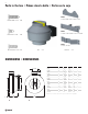
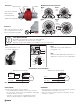
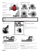
Illustration 2
Mounting Bracket & Screw Locations for FG
Fans may be suspended
without special
mounting brackets.
Clamp Fastener Duct Fan
Spiral duct
Vibration absorbing material
Models
• 4
• 5
Models
• 4XL
• 5XL
Models
• 6
Models
• 6XL
• 6M
• 8/8XL
• 10/10XL
SPECIAL WIRING PRECAUTIONS
All installation should be wired according to the following diagrams.
Failure to comply will cause the motor to “hum” or not work.
Maximum torque that can be applied to the terminal block screws is 0.79 Nm (7 lb-in).
TROUBLESHOOTING
If fan fails to operate, please check the following:
a. Consult wiring diagrams included to ensure proper connections.
b. To ensure proper contact, check motor lead wiring, incoming supply
wiring and capacitor connections.
c. If possible, use a meter to test for continuity between fan leads.
Please note capacitor will show no reading if tested with meter.
MAINTENANCE
1. Since fan bearings are sealed and have been provided with an internal
lubricating material, no lubrication is necessary.
2. Once a year, remove any airborne particles in the impeller. No other
maintenance is required.
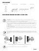
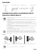
INSTRUCTION FOR 120V and 230V MOTORS
Motor
Speed
Control
Capacitor
Motor
Black (L)
White (N)
Green (GND)
Green
Brown
Black
Blue
With motor speed controller
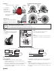
Capacitor
Motor
Brown
Black
Blue
Without motor speed controller
Brown
Capacitor
Blue
Ground
Ground
Black
Green/Yellow
N
N
L
N
L
Capacitor
L
N
Ground
Supply voltage
Brown
Motor
Leads
L (Black)
N (White)
Ground
Black
Blue
Green/Yellow
Capacitor
3 wire motor 4 wire motor
Note:
Model FGC comes pre-wired with three
prong power cord.
Note:
Cable gland must be used
for outside applications.
Green
Black (L)
White (N)
Green (GND)
Note: Select control based on line voltage
Note:
Fans are furnished with either 120V motors or
230V motors. The motors are not dual voltage.
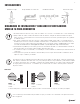
When connecting duct to the fan, do
not screw less than 1/2" from the
housing, it may block the blades.
Ilustration 3
1/2"