GE Fanuc Automation Programmable Control Products VersaMax™ System Genius® Network Interface Unit User's Manual GFK-1535A November 2000
GFL-002 Warnings, Cautions, and Notes as Used in this Publication Warning Warning notices are used in this publication to emphasize that hazardous voltages, currents, temperatures, or other conditions that could cause personal injury exist in this equipment or may be associated with its use. In situations where inattention could cause either personal injury or damage to equipment, a Warning notice is used. Caution Caution notices are used where equipment might be damaged if care is not taken.
Contents Chapter 1 Introduction............................................................................................ 1-1 Related Manuals.................................................................................................. 1-2 The VersaMax Family of Products ................................................................... 1-3 The VersaMax Genius I/O Station ....................................................................... 1-4 The Genius NIU......................................
Contents Autoconfiguration of the Genius NIU and I/O Station ........................................ 4-10 How Autoconfiguration Handles Equipment Changes........................................ 4-13 Chapter 5 Datagrams .............................................................................................. 5-1 Datagram Types .................................................................................................. 5-2 Read Map ................................................................
Chapter Introduction 1 This manual explains how to install and use a VersaMax™ Genius® Network Interface Unit module to interface VersaMax I/O modules to a Genius bus. NIU installation procedures are described in Chapter 2. NIU operation is described in chapter 3. This chapter explains how the NIU interacts with the modules in its station, how it stores data, and how it exchanges data with the system host. Configuration is described in chapter 4.
1 Related Manuals 1-2 VersaMax Modules, Power Supplies, and Carriers User’s Manual (catalog number GFK-1504) Describes the many VersaMax I/O and option modules, power supplies, and carriers. This manual also provides detailed system installation instructions. Remote I/O Manager User’s Guide (catalog number GFK-1847). Gives step-by-step instructions for using the Remote I/O Manager configuration software.
1 The VersaMax Family of Products The VersaMax family of products provides universally-distributed I/O that spans PLC and PC-based architectures. Designed for industrial and commercial automation, VersaMax I/O provides a common, flexible I/O structure for local and remote control applications. The VersaMax PLC provides big-PLC power with a full range of I/O and option modules.
1 The VersaMax Genius I/O Station A VersaMax PLC consists of a group of VersaMax modules with a VersaMax CPU and attached power supply in the first position. Genius NIU VersaMax Modules power supply An I/O Station provides up to 64 analog channels and up to 1024 discrete points for 256 total bytes of I/O. The NIU operates as a device on a Genius bus, automatically exchanging I/O, diagnostic, and control data with a PLC or host computer.
1 The Genius NIU The VersaMax Genius Network Interface Unit (IC200GBI001) interfaces a VersaMax I/O Station to a Genius I/O bus. The system host can be any PLC or computer capable of controlling the Genius bus. E GBI001 PWR OK FAULT I/O ENBL FORCE IC200GBI001 Genius® NIU SBA ERR BUS B U 0 1 A N 2 3 SBA X10 2 3 SBA X1 2 3 BAUD RATE 9 0 1 8 7 N 6 5 4 0 1 THIS DEVICE COMPLIES WITH PART 15 OF THE FCC RULES.
1 Genius NIU Specifications Number of Modules 8 per rack, 64 per NIU/station Network inputs per bus scan 128 bytes Network outputs per bus scan 128 bytes Discrete Input Memory 1024 points Discrete Output Memory 1024 points Analog Input Memory 64 channels Analog Output Memory 64 channels Power Consumption +5V@250mA, +3.3V@10mA Serial Bus Address 0 to 31 Network data rate 153.6 Kbaud extended, 153.6 Kbaud standard, 76.8 Kbaud, or 38.4 Kbaud.
1 Power Supplies An AC or DC Power Supply module installs directly on the NIU. The Power Supply provides +5V and +3.3V power to the modules in the station. Additional power supplies can be installed on special booster carriers if needed for systems where the number of modules creates the need for a booster. No booster supply is needed to power conventional I/O modules. 24 VDC, 11 W POWER SUPPLY WARNING: EXPLOSION HAZARD WHEN IN HAZARDOUS LOCATIONS TURN OFF POWER BEFORE REPLACING OR WIRING MODULES.
1 I/O Modules VersaMax IO and option modules are approximately 110mm (4.3in) by 66.8mm (2.63in) in size. Modules can be mounted either horizontally or vertically on several types of available I/O Carriers. Modules are 50mm (1.956 in) in depth, not including the height of the carrier or the mating connectors. 110mm (4.33in) FLD OK 66.8mm (2.
1 Available I/O Modules The following types of VersaMax I/O Modules are available: Discrete Input Modules Input 120VAC 8 Point Grouped Module IC200MDL140 Input 240VAC 8 Point Grouped Module IC200MDL141 Input 120VAC 8 Point Isolated Module IC200MDL143 Input 240VAC 4 Point Isolated Module IC200MDL144 Input 120VAC (2 Groups of 8) 16 Point Module IC200MDL240 Input 240VAC (2 Groups of 8) 16 Point Module IC200MDL241 Input 120VAC 16 Point Isolated Module IC200MDL243 Input 240VAC 8 Point Isolated Modu
1 Discrete Mixed I/O Modules Mixed 24VDC Positive Logic Input Grouped 20 Point / Output Relay 2.0A per Point Grouped 12 Point Module IC200MDD840 Mixed 24VDC Positive Logic Input 20 Point / Output 12 Point / (4) High Speed Counter, PWM, or Pulse Train Configurable Points IC200MDD841 Mixed 16 Point Grouped Input 24VDC Pos/Neg Logic / 16 Pt Grouped Output 24VDC Pos. Logic 0.5A w/ESCP IC200MDD842 Mixed 24VDC Positive Logic Input Grouped 10 Point / Output Relay 2.
1 Carriers Carriers provide mounting, backplane communications, and field wiring connections for all types of VersaMax modules. I/O modules can be installed on carriers or removed without disturbing field wiring. There are three basic I/O Carrier types: Terminal-style I/O carriers. Modules mount parallel to the DIN rail. Compact Terminal-style I/O Carriers. Modules mount perpendicular to the DIN rail. Connector-style I/O Carriers. Modules mount perpendicular to the DIN rail.
1 Available I/O Carriers and Terminal Strips The following types of I/O Carriers, terminals, and cables are available: Terminal-Style I/O Carriers Barrier-Style Terminal I/O Carrier IC200CHS001 Box-Style Terminal I/O Carrier IC200CHS002 Spring-Style Terminal I/O Carrier IC200CHS005 Compact Terminal-Style I/O Carriers Compact Box-Style I/O Carrier IC200CHS022 Compact Spring-Style I/O Carrier IC200CHS025 Connector-Style I/O Carrier Connector-Style I/O Carrier IC200CHS003 Interposing Terminals for
1 Expansion Modules Expansion modules can be used to extend the I/O Station and add more modules. There are two basic types of VersaMax I/O expansion systems, Multi-Rack and Two-Rack Local: Multi-Rack: A VersaMax PLC or NIU I/O Station with an Expansion Transmitter Module (IC200ETM001) and one to seven expansion “racks”, each with an Expansion Receiver Module (IC200ERM001 or IC200ERM002). If all the Expansion Receivers are the Isolated type (IC200ERM001), the maximum overall cable length is 750 meters.
1 VersaMax Modules for Expansion Racks All types of VersaMax I/O and communications modules can be used in expansion racks.
1 VersaMax General Product Specifications VersaMax products should be installed and used in conformance with productspecific guidelines as well as the following specifications: Environmental Vibration Shock Operating Temp. Storage Temp.
Installation Chapter 2 This section gives instructions for installing the Network Interface Unit and the Genius® bus.
2 Module Clearance Maintain a clearance of 2 inches (5.1cm) above and below the equipment and 1 inch (2.54cm) to the left. Additional clearance requirements are shown below. 1 2 133.4mm (5.25in) 85.9mm (3.38in) 3 2-2 1. Allow sufficient finger clearance for opening NIU door. 2. Allow adequate clearance for communications cables. 3. Allow adequate space for power wiring.
2 Thermal Considerations The thermal performance specified for VersaMax I/O modules requires a clearance of 2 inches (5.1cm) above and below the modules and 1 inch (2.54cm) on each side of the modules as shown below, regardless of the orientation of the DIN rail. When using a vertical DIN rail, the NIU module must be installed at the bottom. 5.1cm (2.0in) 2.54cm 2.54cm (1.0in) 2.54cm (1.0in) 5.1cm (2.0in) 5.1cm (2.0in) 5.1cm (2.0in) NIU at Bottom 2.54cm (1.
2 Mounting Instructions Each rack in a VersaMax I/O Station must be installed on a single section of 7.5mm X 35mm DIN rail. “Rack” is the term used for an NIU or Expansion Receiver, plus up to 8 physically-connected I/O carriers. The first rack in a system is called Rack 0. If there are multiple expansion racks, Rack 0 also includes an Expansion Transmitter module installed in the leftmost position, before the NIU.
2 Panel-Mounting For maximum resistance to mechanical vibration and shock, the DIN-rail-mounted module must also be installed on a panel. Using the module as a template, mark the location of the module’s panel-mount hole on the panel. Drill the hole in the panel. Install the module using an M3.5 (#6) screw in the panel-mount hole. Note 1. Tolerances on all dimensions are +/-0.13mm (0.005in) non-cumulative. Note 2. 1.1-1.4Nm (10-12 in/lbs) of torque should be applied to M3.
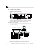
2 Installing an Expansion Transmitter Module If the I/O Station will have more than one expansion rack or one expansion rack that uses an Isolated Expansion Receiver Module (IC200ERM001) as its interface to the expansion bus, an Expansion Transmitter Module must be installed to the left of the NIU. The Expansion Transmitter Module must be installed on the same section of DIN rail as the rest of the modules in the main “rack” (rack 0).
2 Installing an Expansion Receiver Module An Expansion Receiver Module (IC200ERM001 or 002) must be installed in the leftmost slot of each VersaMax expansion “rack”. 1. Insert the label inside the access door at the upper left corner of the module. 2. Attach the module to the DIN rail at the left end of the expansion rack. 3. Select the expansion rack ID (1 to 7) using the rotary switch under the access door at upper left corner of the module. Duplicate Rack IDs are not permitted.
2 Connecting the Expansion Cable: RS-485 Differential For a multiple-rack expansion system, connect the cable from the expansion port on the Expansion Transmitter to the Expansion Receivers as shown below. If all the Expansion Receivers are the Isolated type (IC200ERM001), the maximum overall cable length is 750 meters. If the expansion bus includes non-isolated Expansion Receivers (IC200ERM002), the maximum overall cable length is 15 meters.
2 Connecting the Expansion Cable: Single-ended For a system with one non-isolated expansion rack (IC200ERM002) and NO Expansion Transmitter, connect the expansion cable from the serial port on the VersaMax NIU to the Expansion Receiver as shown below. The maximum cable length is one meter. Cables cannot be fabricated for this type of installation; cable IC200CBL600 must be ordered separately. Note: Do not disconnect an expansion cable while the system is operating.
2 Installing Power Supply Modules Power supply modules install directly onto the NIU module, Expansion Receiver Modules, and supplementary power supply carriers. The power supply provides +5V and +3.3V to downstream modules through the mating connector. The number of modules that can be supported depends on the power requirements of the modules. Additional booster power supplies can be used as needed to meet the power needs of all modules.
2 Installing Additional Modules Before joining carriers to the NIU, remove the connector cover on the righthand side of the NIU. Do not discard this cover; you will need to install it on the last carrier. It protects the connector pins from damage and ESD during handling and use. Do not remove the connector cover on the lefthand side.
2 Setting the SBA and Baud Rate Open the clear protective door by pulling upward at the indentation in the side of the NIU. Use a 2.44mm (3/32in) flat screwdriver to adjust the rotary switches. (Refer to the heading Special Switch Settings if the NIU is being configured using datagrams or for information about upgrading the NIU firmware).
2 Special Switch Settings on the NIU The lettered positions of the rotary switches can optionally be used to: Use a serial bus address that has been sent from the network. Use a baud rate that has been sent from the network. Re-enable autoconfiguration. Put the NIU in “bootloader” mode to accept a firmware upgrade.
2 Overriding a Network Configuration The NIU can also be configured via a message from the network. A network configuration can be set up to deliberately disable the auto-configuration function. If autoconfiguration has previously been disabled by a network configuration, you can restore the autoconfiguration function by following the steps below. 1. Set the upper SBA select switch (SBAx10) on the NIU to the A position.
2 Selecting a Cable Type Proper cable selection is critical to successful operation of the system. Each bus in the system can be any cable type listed in the table below. Cable # & Make NEC (USA) Type Outer Diameter Terminating Resistor* -10%to+20% Number of Conductors/ AWG Dielectric Voltage Rating Ambient Temp Rating (A)9823 (C)4596 (M)M39240 none CL2 CM .350in 8.89mm 153.6s 153.6e 76.8 38.
2 NEC classes are based on data obtained from manufacturers and are subject to change. CANADIAN CEC codes are similar. Other countries may vary. The serial bus can be treated as a Class 2 circuit when appropriate wiring practices are followed. Maximum available bus lengths may be affected when installation requires the high voltage CM (Communications) rating. CM types can replace CL2, but not vice versa. Do not mix cables of different impedance, regardless of cable run length.
2 Using Other Cable Types The cable types listed in the preceding table are recommended. If the cable types listed above are not available, the cable selected must meet the following guidelines. 1. High quality construction. Most important is uniformity of cross section along the length of the cable. Poor quality cable may cause signal distortion, and increase the possibility of damage during installation. 2.
2 Making Bus Connections The NIU has two bus connectors. The upper connector is for the main bus cable; it is always used. The lower connector is for an optional redundant bus cable. The NIU has built-in bus switching capability. In a dual-bus installation, do not attach a separate bus switching device to the NIU. (The NIU can be located on a bus stub downstream of a bus-switching device, however). The maximum exposed length of unshielded wires should be 5cm (2in).
2 Lightning Transient Suppression Running the bus cable outdoors or between buildings may subject it to lightning transients beyond the 1,500 volt transient rating of the system. Installing cable underground reduces the probability of a direct lightning strike. However, buried cables can pick up hundreds of amperes of current when lightning contacts the ground nearby. Therefore, it is important to protect the installation by including surge protectors on underground data lines.
2 Observing the LEDs The LEDs indicate the presence of power and show the operating mode and status of the NIU. PWR OK FAULT I/O ENBL FORCE PWR Indicates that the NIU is receiving power. OK Indicates diagnostics executed successfully. FAULT Is ON if there are one of more faults. I/O ENBL This bicolor LED is green if the I/O scan is enabled and data is being received from the bus. Otherwise, this LED is amber. FORCE Is ON if one of more I/O points is forced* or bus switching is forced.
2 CE Mark Installation Requirements The following requirements for surge, electrostatic discharge (ESD), and fast transient burst (FTB) protection must be met for applications that require CE Mark listing: GFK-1535A The VersaMax I/O Station is considered to be open equipment and should therefore be installed in an enclosure (IP54). This equipment is intended for use in typical industrial environments that utilize anti-static materials such as concrete or wood flooring.
Chapter Operation 3 This section explains how the NIU interacts with the modules in its station, how it stores data, and how it exchanges data on the bus. NIU data memories Scanning inputs and outputs in the I/O Station Data transfer between the Genius NIU and the bus Genius bus scan time Genius Hand-held Monitor Use The Network Interface Unit does not have a Hand-held Monitor connection. A Genius Hand-held Monitor cannot be used to configure, monitor I/O, or force and unforce I/O.
3 NIU Data Memories All of the data for the I/O station utilizes the NIU's four I/O data memories. The NIU has 128 bytes of memory available for each of the four types of data (discrete inputs and outputs, data types I and Q, and analog inputs and outputs, data types AI and AQ). During NIU configuration, data for individual modules is assigned to specific areas of this memory.
3 Scanning Inputs and Outputs in the I/O Station The NIU performs a regular I/O scan of all inputs and outputs. During each I/O scan, the NIU reads inputs from all discrete and analog input modules and places the data into its I and AI memories. The NIU also sends outputs from its Q and AQ memories to all discrete and analog output modules.
3 Data Transfer Between the NIU and the Bus Each bus scan, an NIU exchanges the following data with the bus: It sends an input message with up to 128 bytes of discrete and/or analog inputs. It receives an output message with up to 128 bytes of discrete and/or analog outputs. The exact length of these messages is determined by the network I/O map configured for the NIU.
3 Input Data Format When the NIU takes its turn on the bus, it sends one input data message containing the latest values for all configured discrete inputs followed by all configured analog inputs. Because they are broadcast, they can be obtained by any bus controller on the bus.
3 Output Data Format Each time the PLC or computer that controls the NIU has the bus communications token, it sends fresh output data on the bus. Outputs for the NIU are sent in one output data message, with all configured discrete outputs followed by all configured analog outputs.
3 Genius Bus Scan Time The Genius bus scan time is dependent on the number of devices and amount of data traffic on the bus. The bus scan time may vary from 3-400ms, but 20-30ms is typical. It cannot be less than 3ms. The Genius bus scan time contribution for the NIU depends on its I/O data usage. The table below shows the scan time contribution, at each baud rate, for stations with a total of 16, 32, 64, 128, and 256 bytes, when the NIU receives outputs from only one bus controller at a time.
3 Timing Responsiveness If an output in the station is tied to an input in the same station, the output changes state (or value, in the case of an analog output module) within a few milliseconds of the new output being sent from the bus controller to the NIU. (To guarantee that an output changes state, that state must be present for at least one NIU sweep time or one Genius bus scan time, whichever is greater.
Configuring a Genius NIU and I/O Station Chapter 4 This chapter explains how a Genius NIU and the modules in an I/O Station can be configured. Configuration determines certain characteristics of module operation and also establishes the program references that will used by each module in the system.
4 Using Autoconfiguration or Programmer Configuration The Genius NIU and I/O Station can be either autoconfigured, or configured from a programmer using the Remote I/O Manager configuration software. The choice of which configuration method to use depends on the nature of the system. Autoconfiguration Autoconfiguration is done by the NIU itself. It provides a default configuration for the NIU and I/O Station and does not require the use of a programmer.
4 Configuring “Racks” and “Slots” Even though a VersaMax I/O Station does not have a module rack, both autoconfiguration and software configuration use the traditional convention of “racks” and “slots” to identify module locations. Each logical rack consists of the NIU or an Expansion Receiver module plus up to 8 additional I/O and option modules mounted on the same DIN rail. Each I/O or option module occupies a “slot”. The module next to the NIU or Expansion Receiver module is in slot 1.
4 In an I/O Station that has one expansion rack attached to the expansion bus by a non-isolated Expansion Receiver Module (IC200ERM002), the expansion rack must be configured as rack 1. VersaMax I/O Station Main Rack PS NIU 1M VersaMax Expansion Rack PS ERM In an I/O Station with an Expansion Transmitter Module (IC200BTM001) and up to seven expansion “racks”, each with an Expansion Receiver Module (IC200ERM001 or IC200ERM002), the additional racks are configured as rack 1 through rack 7.
4 Software Configuration of the Genius NIU and I/O Station Software configuration provides greater flexibility than autoconfiguration in setting up an I/O Station. Software configuration is done using the Remote I/O Manager configuration software. The software is available with a programmer cable as catalog number IC641CFG110, or without a programmer cable as catalog number IC641CFG100. It can also be done using the VersaPro programming/configuration software, version 1.5 or later.
4 Basic Steps of Software Configuration The Remote I/O Manager software provides a simple default configuration that you edit to match the actual system modules. The default configuration consists of a power supply (PWR001) and an NIU (either a Genius NIU or the NIU that was saved last time the software was used). Carriers and modules are then added in the same sequence as the hardware installation. The basic configuration steps are listed below.
4 Configuring NIU Parameters NIU configuration establishes the basic operating characteristics of the Network Interface Unit. When a programmer is first connected, the NIU communicates using the default communications parameters: 19,200 baud, odd parity, one start bit, one stop bit, and eight data bits. If these parameters are re-configured, the new configuration for the serial port is not actually installed until the programmer is removed.
4 Software Configuration: Load, Store, Verify, Clear To transfer and check the contents of a configuration, use the Load/Store/Verify functions from the Tools menu. A configuration file must be saved in the programmer before using the load/store/verify functions. The computer connects to the expansion port. on the side of the Genius NIU or the pass-through serial port on an Expansion Transmitter Module.
4 Storing a Configuration to the Genius NIU After completing a configuration in the programmer, the configuration must be stored to the Genius NIU. In the Tools menu, select Load/Store/Verify and click on Store. When a configuration is stored, the NIU automatically drops off the bus until the store is complete. The NIU then comes back on the bus. Storing a configuration disables autoconfiguration, so the NIU will not overwrite a software configuration with an autoconfiguration during subsequent startups.
4 Autoconfiguration of the Genius NIU and I/O Station Autoconfiguration is done by the NIU itself. It provides a default configuration for the NIU and I/O Station and does not require the use of a programmer. I/O modules that have software-configurable features always use their default settings when autoconfigured. When autoconfiguration is enabled and no previous autoconfiguration exists, at powerup the NIU automatically reads the default configuration of the modules installed in the system.
4 Autoconfiguration Assigns Reference Addresses The NIU stores data internally as discrete input bits, discrete output bits, analog input words, and analog output words. The NIU Data Memories I discrete input bits AI analog input words Q discrete output bits AQ analog output words During autoconfiguration, the NIU automatically looks at the modules installed in the I/O Station and assigns them to addresses in this internal I/O map. Reference addresses are assigned in ascending order.
4 Autoconfiguring an I/O Station with Expansion Racks 4-12 The Expansion Receiver modules must have their rack ID selection dials set correctly. Any available rack number can be used for a new expansion rack but they must all be unique (no duplicate rack numbers). It is best to assign expansion racks numbers from lowest (1) to highest (7) as they are installed.
4 How Autoconfiguration Handles Equipment Changes Previously-configured modules are not removed from the configuration during autoconfiguration unless no modules are present in the system during the autoconfiguration. Module Present But Non-Working During Autoconfiguration: if a module is physically present but not working during autoconfiguration, the module is not configured and the NIU generates an extra module diagnostic.
Chapter Datagrams 5 This section lists datagrams that can be sent to or from a Genius Network Interface Unit, and shows the datagrams for VersaMax modules that are different from the formats used by other modules. It also shows the format of configuration data for the Network Interface Unit and the modules in the station.
5 Datagram Types The table below shows the primary datagrams that may be acted upon by the NIU.
5 Read Map Subfunction Code: 2A hex This datagram is used to read the reference addresses and lengths that have been configured for the NIU's network I/O map. Data Field Format: none Read Map Reply Subfunction Code: 2B hex An NIU sends this reply datagram after receiving a Read Map datagram. It contains the previously-configured NIU network map addresses. The network map defines the NIU memory locations of the data that is exchanged on the bus.
5 Report Fault Datagram Format The format of Report Fault datagrams sent by an NIU is shown below. A Series 90 PLC interprets this information automatically; no datagram programming is required. If the host is a Series Six or Series Five PLC, this information is ignored. If the host is a computer, this information can be retrieved from the unsolicited datagram queue, and interpreted as needed for the application. Note: The NIU can store up to 32 untransmitted fault messages.
5 Fault Byte 3 byte 2 7 6 5 4 3 2 1 0 Fault record number (always 1) Number of fault records (always 1) Fault Bytes 4 and 5 Fault bytes 4 and 5 (bytes 3 and 4 of the datagram) identify the reference offset (within the NIU itself) assigned to the faulted module. This is an internal reference.
5 Configuration Data Datagrams can be used to read and write configuration data for an I/O Station. However, most systems will instead use the Remote I/O Manager or VersaPro software for configuration. For a Network Interface Unit, the configuration data specifies the “rack” and slot number of a specific device in the station.
5 Read Configuration Reply Data Subfunction Code: 03 hex This datagram is a reply to the Read Configuration datagram. Bytes 0-5 are like the Read Configuration datagram above. Bytes 6-133 contain the module data, and are like the Write Configuration datagram.. Read Configuration Data Format Byte # 0 1, 2 3 4, 5 6 - 31 32 to end Description Rack Number (0,…, 7) Length (must match the length for the specific device whose configuration will be written. Maximum=128) Slot (0,…, 9.
5 Write Configuration Data Subfunction Code: 04 hex The Write Configuration datagram is used to send configuration data for the NIU or a module in the I/O Station. The context-dependent slot configuration data is the same as the Read Configuration Reply. For each “rack” in the I/O Station, slot 0 configuration data includes the power supply, I/O carriers, and any booster power supplies present.
5 Power Supply and Carriers Configuration Data Format (Rack 0-7, slot 0) (Byte in Message) 6, 7 8 9 GFK-1535A (Byte in Record) 0, 1 2 3 10,…, 13 4,…, 7 14 15 16, 17 18 19 20, 21 8 9 10, 11 12 13 14, 15 22,…, 29 30, 31 32, 33 34 35 36,…, 39 40 16,…, 23 24, 25 0, 1 2 3 4,…, 7 8 41 42 43 44 45 46 47 48,…, 55 56, 57 9 10 11 12 13 14 15 16,..
5 Power Supply and Carriers Configuration Data Format (continued) (Byte in Message) (Byte in Record) 58, 59 60 61 62,…, 65 66 0, 1 2 3 4,…, 7 8 67 68 69 70 71 72 73 74 75 76 77 78 79 80,…, 81 82, 83 9 10 11 12 13 14 15 16 17 18 19 20 21 22,….
5 Network Interface Unit Configuration Data Format (Rack 0, slot 1) (Byte in Message) 6, 7 (Byte in Record) 0, 1 Byte Description 8 2 major type (03=NIU) 9 3 minor type (01) 10,…, 13 4,…, 7 14 8 15,…, 29 9,…, 23 not used, must be 0 30, 31 24, 25 Length of additional data (52) 32, 33 34 0, 1 2 not used (00,00) reserved (must be 00, 00, 00, 00) autoconfiguration enable (enabled=1) not used (00,00) major type (05=Expansion Module) 35 3 36,…, 39 40,…, 55 4,…, 7 8,… 23 reserved (must
5 Expansion Receiver Module Format (Rack 1-7, slot 1) 5-12 (Byte in Message) (Byte in Record) Byte Description 6, 7 0, 1 8 2 major type (05=Expansion Module 9 3 Type of Expansion Receiver (02=Isolated, 03=Non-isolated) 10,…, 13 4,…, 7 not used (must be 0) 14,…, 29 8,…, 23 not used (must be 0) 30, 31 24, 25 Length of additional data (0) not used (must be 0) VersaMax™ System Genius® Network Interface Unit User's Manual – November 2000 GFK-1535A
5 I/O Module Format Configuration data follows the same format for all non-intelligent I/O modules, analog or discrete, input, output or mixed. The configuration datagram contains a VersaMax configuration message header, a rack/slot header, fixed I/O configuration fields, variable-length configuration fields and module-specific data. The total length of fixed and variable I/O configuration fields and module-specific data must be a multiple of 26 bytes.
5 I/O Module Format (Rack 0-7, slot 2-9) (continued) (Byte in Message) (Byte in Record) Byte Description Optional I/O configuration fields 56,… N Input segments list, an eight-byte reference description field for each discrete or analog input segment, see below. Output segments list, an eight-byte reference description field for each discrete or analog output segment. Input segments mode, a bitmapped word with a bit representing each reference description in the input segments list.
5 The NIU fills out the configuration data fields based on the content of the primary and secondary board ID fields. The NIU reads these fields from the I/O module. Bit fields in the module board ID indicate whether the module is discrete or analog, the number of input points or channels, the number of output points or channels and whether diagnostic bits are returned by the module. The NIU calculates values of the fixed and variable-length configuration fields from these parameters.
5 Module-specific data is unique to the type of module. For analog and discrete I/O modules, two bytes of module-specific data are returned. The content of these bytes is defined in the following tables.
5 Example: Configuration message for IC200MDD844 The following example shows the Read Configuration Data Reply datagram for a mixed discrete I/O module, the IC200MDD844. This module contains a 16-point output board as its primary board and a 16-point input board as its secondary slot.
5 5-18 (Byte in Message) (Byte in Record) Content 0 1, 2 3 4,5 0 1, 2 3 4,5 0 82 3 0, 0 6, 7 8, 9 10,…, 13 0, 1 2, 3 4,…, 7 14,…, 29 30, 31 8,…, 23 24, 25 0x80, 0x08 0x80, 0x80 0x44, 0x38, 0x34, 0x34 0 50, 0 32, 33 0, 1 0x80, 0x08 34, 35 2, 3 0x80, 0x80 36, 37 4, 5 48, 0 38, 39 6, 7 1, 0 40, 41 8, 9 1, 0 42, 43 10, 11 0, 0 44, 45 12, 13 0, 0 46, 47 14, 15 3, 0 48, 49 50, 51 52, 53 54, 55 16, 17 18, 19 20, 21 22, 23 0, 0 2, 0 0, 0 0, 0 Byte Description VersaMax configu
5 Example: Configuration message for IC200MDD844, a mixed discrete I/O module (continued) (Byte in Message) GFK-1535A (Byte in Record) Content 56 57 58, 59 24 25 26, 27 1 16 17, 0 60, 61 62, 63 28, 29 30, 31 2, 0 44, 0 64 65 66, 67 32 33 34, 35 2 18 8, 0 68, 69 70, 71 72 36, 37 38, 39 40 2, 0 46, 0 0, 0 74 42 0, 0 76 77 44 45 0 0 78 79 46 47 0xFF 0xFF 80 48 2 81 82, 83 49 50, 51 0 0, 0 Chapter 5 Datagrams Byte Description Optional I/O configuration fields Input segments list,
5 Set NIU Operating Mode Subfunction Code: 39 hex This datagram can be used to set the operating mode of the NIU. Byte No. Byte Description 0 Mode 1 Mode This message has two copies of the mode parameter. These copies must be equal for the command to be accepted by the NIU. If you disable I/O scanning, the NIU sends no inputs and receives no outputs. 7 6 5 4 3 2 1 0 I/O Scan Enable/Disable (1 = enable, 0 = disable) Unused (must be 0) .
Chapter Redundancy 6 Most systems use only one CPU to control the I/O on the Genius bus. CPU redundancy, which can be used for backup CPU/Bus Controller protection in critical applications, is described in detail in the Genius documentation. The discussion that follows summarizes how the NIU can fit into a Genius CPU Redundancy system.
6 CPU/Bus Controller Redundancy In CPU redundancy, two Bus Controllers on the same bus can send control outputs at the same time. Both Bus Controllers automatically receive inputs and fault reports from all devices on the bus that have been configured as being in “CPU Redundancy” mode. The Bus Controllers must use serial bus addresses 30 and 31. VersaMax I/O Stations can be used on a bus controlled by redundant CPUs/Bus Controllers.
6 Using the NIU in a Genius Bus Redundancy System In Genius bus redundancy, there are two bus cables each connected to a Bus Controller or PCIM. I/O devices such as the NIU may be connected to either one bus of the pair, or to both. A device that is connected to both busses actually communicates on only one bus at a time. Before the alternate bus can be used for communications, a bus switchover must occur and the device must “log in” with the Bus Controller(s) on the alternate bus.
6 An NIU can be located on one bus of a redundant bus pair, if bus redundancy is not needed for the modules in that station. In this example, the NIU on the left is connected to both Bus A and Bus B and is configured as a bus switching device. The NIU on the right, which serves non-critical I/O modules, is connected to Bus A only, and is not configured as a bus switching device. Bus A Bus B NIU NIU An NIU can be located on a bus stub.
Appendix Operation of the Genius Bus A This section describes the characteristics of the bus that links Genius devices. This information supersedes the equivalent text portion of chapter 2 of the Genius I/O System and Communications Manual (GEK-90486-1) “The Communications Bus”.
A Electrical Interface All stations must receive in order to track the present token value and take their appropriate turn on the bus, regardless whether the data is to be used locally. The transmit sequence is the same as the serial bus address (SBA) set into each location during configuration.
A Serial Bus Waveforms The actual waveforms seen on the cable depend on the cable impedance and the distance from the station presently transmitting. A data “0” is a series of three AC pulses, while a “1” is no pulse. +Vp +Vr -Vr -Vp 0 1 0 0 1 1 t= baud rate SERIAL 1 VOLTAGE RELATIVE TO SERIAL 2 Use caution when connecting instrumentation to the bus. A differential probe or a summation of two probes relative to ground is required.
A Maximum Bus Length Three effects limit the maximum length bus available at any baud rate: 1. Voltage attenuation 2. Waveform distortion (frequency dispersion) 3. Propagation delays Attenuation The transmitter output levels and receiver thresholds determine the maximum attenuation that can be tolerated. This is the principal determinant when using recommended cables.
A The half cycle pulse width, when measured between the positive and negative receiver thresholds, denoted as Tp/2 in the figure, will vary along the waveform due to dispersion, and resembles a frequency shift.. The digital input filter essentially is a band pass filter which looks at the half cycle timing Tp/2, and the duration above the thresholds, Tw. The limits are: Tp/2 = 0.6 Tp(normal) maximum Tw = 0.
A Serial Data Format The Genius protocol produces maximum throughput of data by using a minimum overhead of control and synchronizing characters. Each character is 11 bits long, comprising a start bit (always 0), next a control bit, followed by 8 bits of data, sent LSB first. The last bit is a stop bit, always 1. Successive characters are sent with no time space between them. The control bit indicates the type of character being sent. A 1 indicates a control character, and 0 a data character.
A Genius Transceiver Electrical Specification Property Min Max Normal peak voltage Vp into 78 ohm terminated cable (1) 3.5 volts 5.5 volts Normal peak voltage Vp into 150 ohm terminated cable (1) 6.0 volts 9.
Performance Data Appendix B This section lists approximate scan times in microseconds for modules in a VersaMax Genius NIU I/O Station. Each module was configured with its default settings and user power was applied when applicable. This information is provided as a guideline for determine I/O scanning times. Actual timing may vary.
B Module Catalog Number B-2 Description Main Rack Expansion Rack Non-isolated IC200MDD844 Mixed 24 VDC Pos/Neg Logic Input Grouped 16 Point / Output 12/24VDC Pos. Logic 0.5A 16 Point Module 780 867 Extended or Isolated 1842 IC200MDD845 Mixed 16 Point Grouped Input 24VDC Pos/Neg Logic / 8 Pt Relay Output 2.0A per Pt Isolated Form A 660 759 1689 IC200MDD846 Mixed 120VAC Input 8 Point / Output Relay 2.
Index A Add modules to autoconfiguration, 4-11 Addition of Module diagnostic, 4-13 Analog outputs, 3-6 Attenuation, A-4 Autoconfiguration, 4-1, 4-2, 4-10 B BIU data types, 3-3 Bus access, A-6 cable characteristics, 2-17 cable types, 2-15 electrical interface, A-2 general transceiver specifications, A-7 length, 2-17 lightning transients, 2-19 outdoors, 2-19 repeaters, using, A-4 scan time, 3-4, 3-7 serial data format, A-1, A-6 surge suppression, 2-19 termination, 2-18 unspecified cable type, using, A-4 usin
Index I I/O carriers, 1-8 installation, 2-4 I/O data transfer with host, 3-4 I/O Modules catalog numbers, 1-9 Inserting modules, 4-11 K Keying dials on carrier, 1-8 L Logicmaster 90-70 software version required, 1-6 Loss of Module diagnostic, 4-13 M Manuals, 1-2 Module color code, 1-8 Module dimensions, 1-8 Module keying, 1-8 Module latch, 1-8 Module orientation on I/O carriers, 1-11 Modules per station, 1-3 Mounting holes, 2-4 O OK LED, 1-8 Operating mode, 5-20 Output defaults, 3-6 Outputs sent by hos