
Network Router User Manual


GFK-1535A Chapter 2 Installation 2-5
2
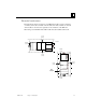
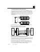
Panel-Mounting
For maximum resistance to mechanical vibration and shock, the DIN-rail-mounted
module must also be installed on a panel. Using the module as a template, mark the
location of the module’s panel-mount hole on the panel. Drill the hole in the panel.
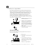
Install the module using an M3.5 (#6) screw in the panel-mount hole.
Note 1. Tolerances on all dimensions are +/-0.13mm (0.005in) non-cumulative.
Note 2. 1.1-1.4Nm (10-12 in/lbs) of torque should be applied to M3.5 (#6-32) steel
screw threaded into material containing internal threads and having a
minimum thickness of 2.4mm (0.093in).
S
EE NOTE 2.
M3.5 (#6) SCREW
1
5.9mm
0
.62in REF
S
PLIT LOCK
WASHER
F
LAT WASHER
N
IU
T
APPED
H
OLE IN
P
ANEL
5
.1mm
0
.200in
4
.3mm
0
.170in
4
.3mm
0
.170in