
Network Router User Manual


GFK-1535A Chapter 2 Installation 2-7
2
Installing an Expansion Receiver Module
An Expansion Receiver Module (IC200ERM001 or 002) must be installed in the
leftmost slot of each VersaMax expansion “rack”.
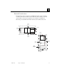
1. Insert the label inside the access door at the upper left corner of the module.
2. Attach the module to the DIN rail at the left end of the expansion rack.
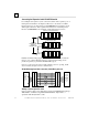
3. Select the expansion rack ID (1 to 7) using the rotary switch under the access
door at upper left corner of the module. Duplicate Rack IDs are not permitted.
In a single-ended expansions system, the receiver Rack ID must be set to 1.
5
7
6
4
1
3
2
0
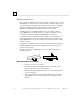
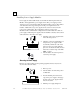
4. Install the Power Supply module on top of the Expansion Receiver.
5. Attach the cables. If the system includes an Expansion Transmitter Module,
attach the terminator plug to the EXP2 port on the last Expansion Receiver
Module.
6. After completing any additional system installation steps, apply power and
observe the module LEDs.
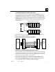
PWR
EXP RX
SCAN
O
n indicates presence of 5VDC power.
B
linking or On indicates module is
c
ommunicating on expansion bus
O
ff indicates module not communicating
G
reen indicates CPU/NIU is OK, has
b
een configuredm and is being scanned.
A
mber indicates not scanning.
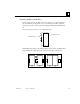
Removing an Expansion Receiver Module
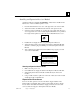
1. Make sure rack power is off.
2. Un-install the Power Supply module from the Expansion Receiver Module.
3. Slide the Expansion Receiver Module on DIN rail away from the other
modules.
4. Using a small screwdriver, pull down on the tab on the bottom of the module
and lift the module off the DIN rail.
Expansion Rack Power Sources
Power for module operation comes from the Power Supply installed on the
Expansion Receiver Module. If the expansion rack includes any Power Supply
Booster Carrier and additional rack Power Supply, it must be tied to the same
source as the Power Supply on the Expansion Receiver Module.