
Network Router User Manual


2-8 VersaMax™ System Genius® Network Interface Unit User's Manual – November 2000 GFK-1535A
2
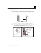
Connecting the Expansion Cable: RS-485 Differential
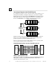
For a multiple-rack expansion system, connect the cable from the expansion port on
the Expansion Transmitter to the Expansion Receivers as shown below. If all the
Expansion Receivers are the Isolated type (IC200ERM001), the maximum overall
cable length is 750 meters. If the expansion bus includes non-isolated Expansion
Receivers (IC200ERM002), the maximum overall cable length is 15 meters.
P
S
C
PU/NIU
P
S
E
RM
P
S
E
RM
E
TM
VersaMax ExpansionRack 1
Terminator
Plug
15M with any
IC200ERM002 ERMs
750M with all
IC200ERM001 ERMs
V
ersaMax PLC or I/O Station Main Rack (0)
VersaMax ExpansionRack 7
Install the Terminator Plug (supplied with the Expansion Transmitter module) into
the lower port on the last Expansion Receiver. Spare Terminator Plugs can be
purchased separately as part number IC200ACC201 (Qty 2).
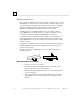
Note: Do not disconnect an expansion cable while the system is operating. It will
cause momentary disruptions in bus communications.
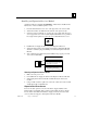
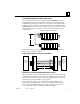
RS-485 Differential Inter-Rack Connection (IC200CBL601, 602, 615)
Expansion
Transmitter or
Expansion
Receiver
Module
Transmitting
Port
PIN
2
3
5
6
8
9
12
13
16
17
20
21
24
25
7
23
1
FRAME+
FRAME-
RIRQ/+
RIRQ/-
RUN+
RUN-
RERR+
RERR-
IODT+
IODT-
RSEL+
RSEL-
IOCLK+
IOCLK-
0V
0V
SHIELD
P
IN
2
3
5
6
8
9
1
2
1
3
1
6
1
7
2
0
2
1
2
4
2
5
7
2
3
1
F
RAME+
F
RAME-
R
IRQ/+
R
IRQ/-
R
UN+
R
UN-
R
ERR+
R
ERR-
I
ODT+
I
ODT-
R
SEL+
R
SEL-
I
OCLK+
I
OCLK-
0
V
0
V
S
HIELD
26-PIN
FEMALE
26-PIN
MALE
2
6-PIN
M
ALE
26-PIN
FEMALE
V
ARIABLE (SEE
T
EXT)
Expansion
Transmitter
or
Expansion
Receiver
Module
Receiving
Port
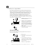
Building a Custom Expansion Cable
Custom expansion cables can be built using Connector Kit IC200ACC202, Crimper
AMP 90800-1, and Belden 8138, Manhattan/CDT M2483, Alpha 3498C, or
equivalent AWG #28 (0.089mm
2
) cable.