
Network Router User Manual


GFK-1535A Chapter 2 Installation 2-9
2
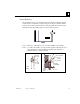
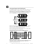
Connecting the Expansion Cable: Single-ended
For a system with one non-isolated expansion rack (IC200ERM002) and NO
Expansion Transmitter, connect the expansion cable from the serial port on the
VersaMax NIU to the Expansion Receiver as shown below. The maximum cable
length is one meter. Cables cannot be fabricated for this type of installation; cable
IC200CBL600 must be ordered separately. Note: Do not disconnect an expansion
cable while the system is operating. It will cause momentary disruptions in bus
communications.
P
S
E
RM
VersaMax Expansion Rack
1 M
V
ersaMax PLC or NIU I/O Station Main Rack
P
S
C
PU/NIU
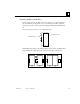
No Terminator Plug is needed in a single-ended installation; however, it will not
impede system operation if installed.
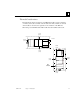
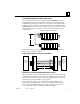
Single-Ended Inter-Rack Connection (IC200CBL600)
PIN
1
2
3
6
9
10
12
16
14
0V
T_IOCLK
T_RUN
T_IODT_
T_RERR
T_RIRQ_
T_FRAME
T_RSEL
0V
P
IN
1
6-PIN
M
ALE
16-PIN
FEMALE
2
6-PIN
M
ALE
26-PIN
FEMALE
1516
12
4
7
2
2
1
4
1
8
1
5
1
1
1
0
1
9
2
3
1
S
INGLE_
0
V
T
_IOCLK
T
_RUN
T
_IODT_
T
_RERR
T
_RIRQ_
T
_FRAME
T
_RSEL
0
V
S
HIELD
1
M
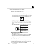
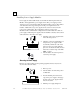
Expansion
Receiver
IC200ERM002
Receiving
Port
VersaMax
CPU or NIU
Serial Port
Power Sources for Single-Ended Expansion Rack Systems
When operating the system in single-ended mode, the power supplies for the main
rack and expansion rack must be fed from the same main power source. The main
rack and expansion racks cannot be switched ON and OFF separately; either both
must be ON or both must be OFF for proper operation.
Power for module operation comes from the Power Supply installed on the
Expansion Receiver Module. If the expansion rack includes any Power Supply
Booster Carrier and additional rack Power Supply, it must be tied to the same
source as the Power Supply on the Expansion Receiver Module.