
Network Router User Manual

GFK-1535A Chapter 5 Datagrams 5-5
5
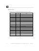
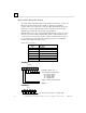
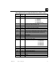
Fault Byte 3
7654 32 10
byte 2
F
ault record number (always 1)
N
umber of fault records (always 1)
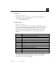
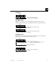
Fault Bytes 4 and 5
Fault bytes 4 and 5 (bytes 3 and 4 of the datagram) identify the reference offset
(within the NIU itself) assigned to the faulted module. This is an internal reference.
76 54 32 10
byte 3
D
iagnostic reference address, LSB
(
always 1)
76 54 32 10
byte 4
D
iagnostic reference address, MSB
(
always 0)
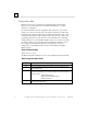
Fault Bytes 6 and 7
Fault bytes 6 and 7 (datagram bytes 5 and 6) are interpreted by a Series 90-70 PLC
automatically. They are not relevant to other types of host.
7654 32 10
byte 5
7654 32 10
byte 6
I
f bit 7 = 1 Number of fault entries to set
I
f bit 7 = 0 Number of the discrete point or analog channel
within the module that has a fault
F
ault entire I/O module
E
ntity offset into diagnostic table
R
eserved