
Network Router User Manual

5-8 VersaMax™ System Genius® Network Interface Unit User's Manual – November 2000 GFK-1535A
5
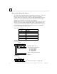
Write Configuration Data
Subfunction Code: 04 hex
The Write Configuration datagram is used to send configuration data for the NIU or
a module in the I/O Station. The context-dependent slot configuration data is the
same as the Read Configuration Reply.
For each “rack” in the I/O Station, slot 0 configuration data includes the power
supply, I/O carriers, and any booster power supplies present. Because configuration
datagrams consider power supplies and carriers to be “slot 0”, this numbering
scheme is different that the actual slot numbering described elsewhere in the
manual. In rack 0, slot 1 configuration is the NIU. In expansion racks 1-7, slot 1 is
used for the Expansion Receiver Module. Up to eight I/O modules per “rack” can be
configured as slots 2 through 9.
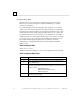
Do not send partial configuration data; it will be rejected by the NIU. If the data is
more than 128 bytes in length, multiple packets may be used. Use the Begin and
End Packet sequence messages to ensure that a sequence of Write Configuration
messages is treated as a single entity. Each packet should be in slot order. Multiple
packets for a slot must also be in order. Multiple packets must be 128 bytes in
length except the last which may be shorter.
Note:
Multiple byte fields in datagrams are transmitted with the least significant
byte of a word in the lowest memory location or transmitted first in time. The most
significant byte follows.
Example:
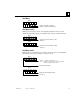
Begin Packet Sequence (subfunction code 06 hex)
Write Configuration 1 (subfunction code 04 hex)
Write Configuration 2
Write Configuration N
End Packet Sequence (subfunction code 07 hex). The total number of BYTES in all Write
Configuration packets. The End Packet Sequence has 2 bytes. Byte 0 is
the least significant byte of the data length; byte 1 is the most significant.
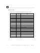
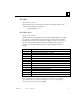
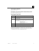
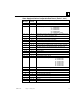
Write Configuration Data Format
Byte # Description
0 Rack Number (0,…, 7)
1 Length of this message (must match the length for the specific device whose
configuration will be written.)
2Slot (0,…, 9. Network Interface Unit is 1)
3 Packet number (0, 1, 2, …)
4, 5 Slot length (bytes)
6 - 31 “Rack/slot” record for the slot
32 to end Context dependent data (optional)