
Network Router User Manual

GFK-1535A Chapter 5 Datagrams 5-9
5
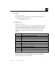
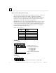
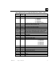
Power Supply and Carriers Configuration Data Format (Rack 0-7, slot 0)
(Byte in
Message)
(Byte in
Record)
Byte Description
6, 7 0, 1 not used (00,00)
8 2 major type (01)
9 3 power supply type: 0 = none
5 = IC200PWR001
10 = IC200PWR002
15 = IC200PWR101
20 = IC200PWR1021
40 = IC200PWB001 (carrier)
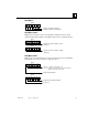
10,…, 13 4,…, 7 ASCII string Set to zeros during auto-configuration, the programmer may
fill this field with an arbitrary identification string.
14 8 2
15 9 Additive checksum for entire station configuration
16, 17 10, 11 CRC checksum for entire station configuration
18 12 number of racks present (1)
19 13 number of slots (maximum 10)
20, 21 14, 15 Feature list (00 00). A bitmapped word reserved for forward compatibility
with future releases. In the initial product release, this value is zero.
22,…, 29 16,…, 23 not used
30, 31 24, 25 Length of additional data (52)
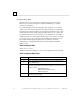
32, 33 0, 1 not used (00,00)
34 2 61h (97)
35 3 9
36,…, 39 4,…, 7 reserved (must be 00, 00, 00, 00)
40 8 first I/O module slot carrier type: 0 = none
5 = IC200CHS001
10 = IC200CHS002
15 = IC200CHS005
20 = IC200CHS010
25 = IC200CHS011
30 = IC200CHS015
35 = IC200CHS003
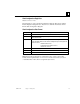
41 9 second I/O module slot carrier type
42 10 third I/O module slot carrier type
43 11 fourth I/O module slot carrier type
44 12 fifth I/O module slot carrier type
45 13 sixth I/O module slot carrier type
46 14 seventh I/O module slot carrier type
47 15 eighth I/O module slot carrier type
48,…, 55 16,.., 23 not used
56, 57 24, 25 Length of additional data (00, 00)