
Network Router User Manual


GFK-1535A Chapter 5 Datagrams 5-17
5
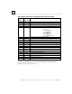
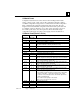
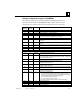
Example: Configuration message for IC200MDD844
The following example shows the Read Configuration Data Reply datagram for a
mixed discrete I/O module, the IC200MDD844. This module contains a 16-point
output board as its primary board and a 16-point input board as its secondary slot.
(Byte in
Message)
(Byte in
Record)
Content Byte Description
VersaMax configuration message header
0 0 0 Rack (e.g., Rack 0, the rack containing the GNIU)
1, 2 1, 2 82 Message length (e.g., 82 bytes total length)
3 3 3 Slot (e.g., 3, the second I/O slot)
4,5 4,5 0, 0 Offset into configuration data
(e.g., zero because the configuration fits in one message)
Rack/slot header
6, 7 0, 1 0x80, 0x08 secondary board ID (e.g., the ID is 0x8008. The LSB is in byte 0, and the MSB is
in byte 1.)
8, 9 2, 3 0x80, 0x80 primary board ID (e.g., the ID is 0x8080. The LSB is in byte 2, and the MSB is in
byte 3.)
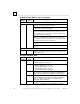
10,…, 13 4,…, 7 0x44, 0x38,
0x34, 0x34
ASCII string. Set to zeros during auto-configuration, the programmer may fill this
field with an arbitrary identification string. (e.g., this is the ASCII label “D844”)
14, 15 8, 9 50, 0 Length of additional data, excluding pad bytes
16,…, 29 10,…, 23 0 not used (must be 0)
30, 31 24, 25 52, 0 Total Length of additional data (e.g., 52 bytes)
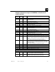
Fixed I/O configuration fields
32, 33 0, 1 0x80, 0x08 secondary board ID (same as above.)
(e.g., discrete DC type, no diagnostic bits, no outputs, eight pairs of inputs)
34, 35 2, 3 0x80, 0x80 primary board ID (same as above)
(e.g., discrete DC type, no diagnostic bits, eight pairs of outputs, no inputs; there
are two boards in this module.)
36, 37 4, 5 48, 0 offset from the start of fixed I/O configuration fields to module-specific data. The
length of module-specific data is given at offset 18 below.
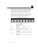
38, 39 6, 7 1, 0 Number of discrete input reference description fields listed in the input
segments list below. (may be 00)
40, 41 8, 9 1, 0 Number of discrete output reference description fields listed in the output
segments list below. (may be 00)
42, 43 10, 11 0, 0 Number of analog input reference description fields listed in the input segments
list below. (may be 00)
44, 45 12, 13 0, 0 Number of analog output reference description fields listed in the output
segments list below.(may be 00)
46, 47 14, 15 3, 0 Module setup, a bitmapped word
bit 0 indicates whether defaults are defined in the configuration structure. If
this bit is ‘1’, then input segments mode, output segments mode, default input
values and default output values fields are included below.
bit 1 enables fault reporting for the module.
bits 2-15 are reserved, must be set to zero.
(e.g., defaults are defined and fault reporting is enabled by this setting.)
48, 49 16, 17 0, 0 Reserved (must be 00)
50, 51 18, 19 2, 0 Length in bytes of module-specific data (e.g., two bytes)
52, 53 20, 21 0, 0 Reserved (must be 00)
54, 55 22, 23 0, 0 Reserved (must be 00)